


System Configuration and Control
www.ti.com
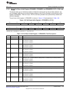
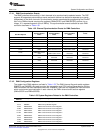
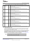
Table 1-51. Pull-Down Inhibit Register 3 (PDINHIBR3) Field Descriptions (continued)
Bit Field Value Description
10 PD10PD Parallel port pin 10 pull-down inhibit bit. Setting this bit to 1 disables the pin's internal pull-down.
0 Pin pull-down is enabled.
1 Pin pull-down is disabled.
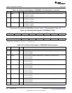
9 PD9PD Parallel port pin 9 pull-down inhibit bit. Setting this bit to 1 disables the pin's internal pull-down.
0 Pin pull-down is enabled.
1 Pin pull-down is disabled.
8 PD8PD Parallel port pin 8 pull-down inhibit bit. Setting this bit to 1 disables the pin's internal pull-down.
0 Pin pull-down is enabled.
1 Pin pull-down is disabled.
7 PD7PD Parallel port pin 7 pull-down inhibit bit. Setting this bit to 1 disables the pin's internal pull-down.
0 Pin pull-down is enabled.
1 Pin pull-down is disabled.
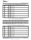
6 PD6PD Parallel port pin 6 pull-down inhibit bit. Setting this bit to 1 disables the pin's internal pull-down.
0 Pin pull-down is enabled.
1 Pin pull-down is disabled.
5 PD5PD Parallel port pin 5 pull-down inhibit bit. Setting this bit to 1 disables the pin's internal pull-down.
0 Pin pull-down is enabled.
1 Pin pull-down is disabled.
4 PD4PD Parallel port pin 4 pull-down inhibit bit. Setting this bit to 1 disables the pin's internal pull-down.
0 Pin pull-down is enabled.
1 Pin pull-down is disabled.
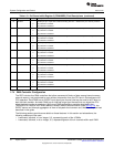
3 PD3PD Parallel port pin 3 pull-down inhibit bit. Setting this bit to 1 disables the pin's internal pull-down.
0 Pin pull-down is enabled.
1 Pin pull-down is disabled.
2 PD2PD Parallel port pin 2 pull-down inhibit bit. Setting this bit to 1 disables the pin's internal pull-down.
0 Pin pull-down is enabled.
1 Pin pull-down is disabled.
1-0 Reserved 0 Reserved.
1.7.4 DMA Controller Configuration
The DSP includes four DMA controllers that allow movement of blocks of data among internal memory,
external memory, and peripherals to occur without intervention from the CPU and in the background of
CPU operation. Each DMA has an EVENT input signal (per channel) that can be used to tell it when to
start the block transfer. And each DMA has an interrupt output (per channel) that can signal the CPU
when the block transfer is completed. While most DMA configuration registers described in the
TMS320C5515/14/05/04 DSP Direct Memory Access (DMA) Controller User's Guide (SPRUFT2), the
EVENT source and interrupt aggregation is more of a system-level concern and, therefore, they are best
described in this guide.
The following sections provide more details on these features. In this section and subsections, the
following notations will be used:
• Lowercase, italicized, n is an integer, 0-3, representing each of the 4 DMAs.
• Lowercase, italicized, m is an integer, 0-3, representing each of the 4 channels within each DMA.
70
System Control SPRUFX5A–October 2010–Revised November 2010
Submit Documentation Feedback
Copyright © 2010, Texas Instruments Incorporated