


Power Management
www.ti.com
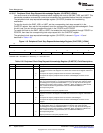
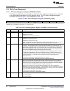
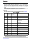
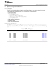
1.5.5 Power Configurations
The power-saving features described in the previous sections, such as peripheral clock gating, and
on-chip memory power down to name a few, can be combined to form a power configuration. Many
different power configurations can be created by enabling and disabling different power domains and clock
domains, however, this section defines some basic power configurations that may be useful. These are
shown and described in Table 1-31. Please note that there is no single instruction or register that can
place the device in these power configurations. Instead, these power configurations are achieved by
modifying multiple registers.
NOTE: Before you change the power configuration, make sure that there is a method for the device
to exit the power configuration. After exiting a power configuration, your software may have
to take additional steps to change the clock and power configuration for other domains.
NOTE: The on-chip Bootloader idles all peripherals and CPU ports at startup. It enables some
peripherals as it uses them. Your application code should check the idle configuration of
peripherals and CPU ports before using them to be sure these are not idle.
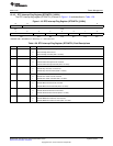
Table 1-31. Power Configurations
Steps to Enter Clock Available Methods for
Power Power Domain and Power Changing/Exiting Clock and
Configuration State Clock Domain State Configuration Power Configuration
RTC only mode DV
DDRTC
, LDOI, Only RTC clock is Set LDO_PD and A. RTC interrupt
and CV
DDRTC
running BG_PD bits in
B. WAKEUP pin
powered all others RTCPMGT register
powered-down
IDLE3 All power domains RTC clock domain Idle peripheral domain A. WAKEUP pin
on enabled
Other clock domains Idle CPU domain B. RTC interrupt
disabled. Clock
generator domain
disabled (BYPASS
MODE and PLL
powerdown).
PLL in BYPASS MODE C. External hardware interrupt (INT0
PLL powerdown or INT1).
Master clock disable D. Hardware Reset
Execute idle instruction
IDLE2 All power domains RTC clock domain Idle peripheral domains A. WAKEUP pin
on enabled
Clock generator domain Idle CPU domain B. RTC interrupt
enabled (PLL_MODE)
Other clock domains Execute idle instruction C. External hardware interrupt
disabled (INT0, INT1).
D. Any unmasked peripheral
interrupt.
E. Hardware Reset
Active All power domains All clock domains Turn on all power
on enabled domains
Enable all clock
domains
50
System Control SPRUFX5A–October 2010–Revised November 2010
Submit Documentation Feedback
Copyright © 2010, Texas Instruments Incorporated