


System Clock Generator
www.ti.com
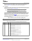
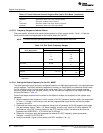
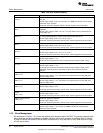
Table 1-9. Clock Generator Control Register Bits Used In PLL Mode (continued)
Register Bit Role in Bypass Mode
RDRATIO Specifies the divider ratio of the reference divider.
M Specify the multiplier value for the PLL.
OUTDIVEN Determines whether the output divider is bypassed.
ODRATIO Specifies the divider ratio of the output divider.
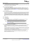
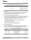
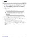
1.4.3.2.3 Frequency Ranges for Internal Clocks
There are specific minimum and maximum frequencies for all the internal clocks. Table 1-10 lists the
minimum and maximum frequencies for the internal clocks for the DSP.
NOTE: For actual maximum operating frequencies, see the device-specific data sheet.
Table 1-10. PLL Clock Frequency Ranges
CV
DD
= 1.05 V CV
DD
= 1.3 V
Clock Signal Name MIN NOM MAX MIN NOM MAX UNIT
CLKIN
(1)
11.289 11.28 MHz
6 96
12 12
12.28
12.288
8
32.76
RTC Clock 32.768 KHz
8
PLLIN 32.0 170 32.0 170 KHz
PLLOUT 60 120 60 120 MHz
0 100 or
SYSCLK 60 or 75 0 MHz
120
PLL_LOCKTIME 4 4 ms
(1)
These CLKIN values are used when the CLK_SEL pin = 1. Bootloader assumes one of these CLKIN
frequencies.
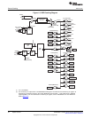
1.4.3.2.4 Setting the Output Frequency for the PLL MODE
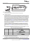
The clock generator output frequency configured based on the settings programmed in the clock generator
control registers. The output frequency depends on primarily on three factors: the reference divider value,
the PLL multiplier value, and the output divider value (see Figure 1-4). Based on the register settings
controlling these divider and multiplier values, you can calculate the frequency of the output clock using
the formulas listed in Table 1-5.
Follow these steps to determine the values for the different dividers and multipliers of the system clock
generator:
1. With the desired clock frequency in mind, choose a PLLOUT frequency that falls within the range listed
in Table 1-10. Keep in mind that you can use the programmable output divider to divide the output
frequency of the PLL.
2. Determine the divider ratio for the reference divider that will generate the PLLIN frequency that meets
the requirements listed in Table 1-10. When possible, choose a high value for PLLIN to optimize PLL
performance. If the DSP is being clocked by the RTC oscillator output, the reference divider must
bypassed (set RDBYPASS = 1); PLLIN will be 32.768 kHz.
3. Determine a multiplier value that generates the desired PLLOUT frequency given the equation:
multiplier = round( PLLOUT/PLLIN ).
4. Using the multiplier, figure out the values for M (PLL multiplier = M + 4).
28
System Control SPRUFX5A–October 2010–Revised November 2010
Submit Documentation Feedback
Copyright © 2010, Texas Instruments Incorporated