


Interrupts
www.ti.com
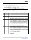
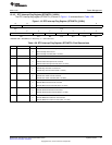
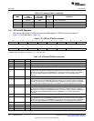
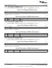
Table 1-32. Interrupt Table (continued)
SOFTWARE RELATIVE
NAME (TRAP) LOCATION PRIORITY FUNCTION
EQUIVALENT (HEX BYTES)
(1)
- SINT28 0xE0 15 Software interrupt #28
- SINT29 0xE8 16 Software interrupt #29
- SINT30 0xF0 17 Software interrupt #30
- SINT31 0xF8 18 Software interrupt #31
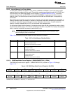
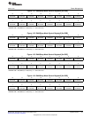
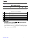
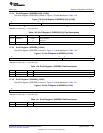
1.6.1 IFR and IER Registers
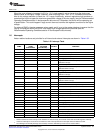
The interrupt flag register 0 (IFR0) and interrupt enable register 0 (IER0) bit layouts are shown in
Figure 1-25 and described in Table 1-33.
Figure 1-25. IFR0 and IER0 Bit Locations
15 14 13 12 11 10 9 8
RCV2 XMT2 SAR LCD PROG3 Reserved PROG2 DMA
R/W-0 R/W-0 R/W-0 R/W-0 R/W-0 R/W-0 R/W-0 R/W-0
7 6 5 4 3 2 1 0
PROG1 UART PROG0 TINT INT1 INT0 Reserved
R/W-0 R/W-0 R/W-0 R/W-0 R/W-0 R/W-0 R-0
LEGEND: R/W = Read/Write; R = Read only; -n = value after reset
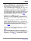
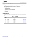
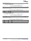
Table 1-33. IFR0 and IER0 Bit Descriptions
Bit Field Value Description
15 RCV2 1-0 I2S2 receive interrupt flag/mask bit.
14 XMT2 1-0 I2S2 transmit interrupt flag/mask bit.
13 SAR 1-0 10-BIT SAR A/D conversion or pin interrupt flag/mask bit.
12 LCD 1-0 LCD interrupt bit.
11 PROG3 1-0 Programmable receive interrupt 3 flag/mask bit. This bit is used as either the I2S1 receive interrupt
flag/mask bit or the MMC/SD1 SDIO interrupt flag/mask bit. The function of this bit is selected
depending on the setting of the SP1MODE bit is in external bus selection register. If SP1MODE =
00b, this bit supports MMC/SD1 SDIO interrupts. If SP1MODE = 01, this bit supports I2S1
interrupts.
10 Reserved 0 Reserved. This bit should always be written with 0.
9 PROG2 1-0 Programmable transmit interrupt 2 flag/mask bit. This bit is used as either the I2S1 transmit
interrupt flag/mask bit or the MMC/SD1 interrupt flag/mask bit. The function of this bit is selected
depending on the setting of the SP1MODE bit in the external bus selection register. If SP1MODE =
00b, this bit supports MMC/SD1 interrupts. If SP1MODE = 01, this bit supports I2S1 interrupts.
8 DMA 1-0 DMA aggregated interrupt flag/mask bit
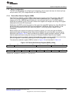
7 PROG1 1-0 Programmable receive interrupt 1 flag/mask bit. This bit is used as either the I2S0 receive interrupt
flag/mask bit or the MMC/SD0 SDIO interrupt flag/mask bit. The function of this bit is selected
depending on the setting of the SP0MODE bit in the external bus selection register. If SP0MODE =
00b, this bit supports MMC/SD0 SDIO interrupts. If SP0MODE = 01, this bit supports I2S0
interrupts.
6 UART 1-0 UART interrupt flag/mask bit
5 PROG0 1-0 Programmable transmit interrupt 0 flag/mask bit. This bit is used as either the I2S0 transmit
interrupt flag/mask bit or the MMC/SD0 interrupt flag/mask bit. The function of this bit is selected
depending on the setting of the SP0MODE bit in the external bus selection register. If SP0MODE =
00b, this bit supports MMC/SD0 interrupts. If SP0MODE = 01, this bit supports I2S0 interrupts.
4 TINT 1-0 Timer aggregated interrupt flag/mask bit.
3 INT1 1-0 External user interrupt #1 flag/mask bit.
2 INT0 1-0 External user interrupt #0 flag/mask bit.
1-0 Reserved 0 Reserved. This bit should always be written with 0.
54
System Control SPRUFX5A–October 2010–Revised November 2010
Submit Documentation Feedback
Copyright © 2010, Texas Instruments Incorporated