


Power Management
www.ti.com
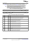
1.5.3.1.1 Idle Configuration Register (ICR) [0001h] and IDLE Status Register (ISTR) [0002h]
Table 1-21 describes the read/write bits of ICR, and Table 1-22 describes the read-only bits of ISTR.
NOTE: To prevent an emulation lock up, idle requests to these domains may be overridden or
ignored when an emulator is connected to the JTAG port of the DSP.
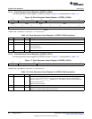
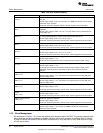
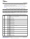
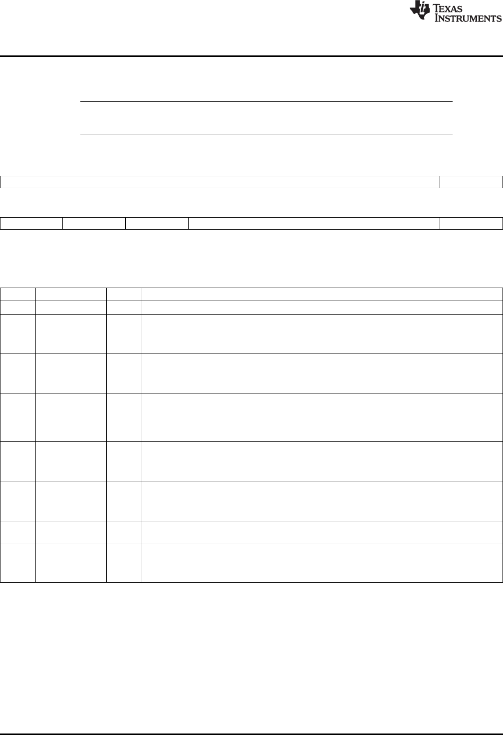
Figure 1-12. Idle Configuration Register (ICR) [0001h]
15 10 9 8
Reserved HWAI IPORTI
R/W-0 R/W-0 R/W-0
7 6 5 4 1 0
MPORTI XPORTI DPORTI IDLECFG CPUI
R/W-0 R/W-0 R/W-0 R/W-0 R/W-0
LEGEND: R/W = Read/Write; -n = value after reset
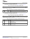
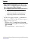
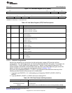
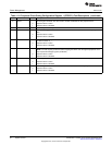
Table 1-21. Idle Configuration Register (ICR) Field Descriptions
Bit Field Value Description
15-10 Reserved 0 Reserved.
9 HWAI FFT hardware accelerator idle control bit.
0 Hardware accelerator remains active after execution of an IDLE instruction.
1 Hardware accelerator is disabled after execution of an IDLE instruction.
8 IPORTI Instruction port idle control bit. The IPORT is used for all external memory instruction accesses.
0 IPORT remains active after execution of an IDLE instruction.
1 IPORT is disabled after execution of an IDLE instruction.
7 MPORTI Memory port idle control bit. The memory port is used for all DMA, LCD DMA, and USB CDMA
transactions into on-chip memory.
0 MPORT remains active after execution of an IDLE instruction.
1 MPORT is disabled after execution of an IDLE instruction.
6 XPORTI I/O port idle control bit. The XPORT is used for all CPU I/O memory transactions.
0 XPORT remains active after execution of an IDLE instruction.
1 XPORT is disabled after execution of an IDLE instruction.
5 DPORTI Data port idle control bit. The data port is used for all CPU external memory data accesses.
0 DPORT remains active after execution of an IDLE instruction.
1 DPORT is disabled after execution of an IDLE instruction.
4-1 IDLECFG 0111b Idle configuration bits. You must always set bit 1, 2 and 3 to 1 and bit 4 to 0 before executing the
idle instruction.
0 CPUI CPU idle control bit.
0 CPU remains active after execution of an IDLE instruction.
1 CPU is disabled after execution of an IDLE instruction.
36
System Control SPRUFX5A–October 2010–Revised November 2010
Submit Documentation Feedback
Copyright © 2010, Texas Instruments Incorporated