


www.ti.com
System Configuration and Control
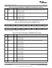
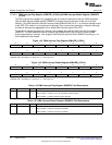
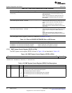
Table 1-59. Peripheral Reset Control Register (PRCR) Field Descriptions (continued)
Bit Field Value Description
5 PG3_RST Peripheral group 3 software reset bit. Drives the MMC/SD0, MMC/SD1, I2S0, and I2S1 reset signal.
Write 0 Writing zero has no effect
Write 1 Writing one starts resetting the peripheral group
Read 0 Reading zero means that peripheral group is out of reset
Read 1 Reading one means the peripheral group is being held in reset and should not be accessed
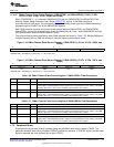
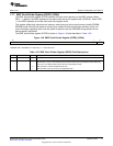
4 DMA_RST DMA software reset bit. Drives the reset signal to all four controllers.
Write 0 Writing zero has no effect
Write 1 Writing one starts resetting the peripheral group
Read 0 Reading zero means that peripheral group is out of reset
Read 1 Reading one means the peripheral group is being held in reset and should not be accessed
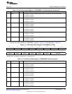
3 USB_RST USB software reset bit. Drives the USB reset signal.
Write 0 Writing zero has no effect
Write 1 Writing one starts resetting the peripheral group
Read 0 Reading zero means that peripheral group is out of reset
Read 1 Reading one means the peripheral group is being held in reset and should not be accessed
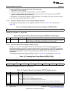
2 SAR_RST SAR software reset bit and reset for most analog-related register in the IO-space address range of
0x7000-0x70FF
Write 0 Writing zero has no effect
Write 1 Writing one starts resetting the peripheral group
Read 0 Reading zero means that peripheral group is out of reset
Read 1 Reading one means the peripheral group is being held in reset and should not be accessed
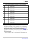
1 PG1_RST Peripheral group 1 software reset bit. Drives the EMIF and all three timer reset signal.
Write 0 Writing zero has no effect
Write 1 Writing one starts resetting the peripheral group
Read 0 Reading zero means that peripheral group is out of reset
Read 1 Reading one means the peripheral group is being held in reset and should not be accessed
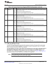
0 I2C_RST I2C software reset bit. Drives the I2C reset signal.
Write 0 Writing zero has no effect
Write 1 Writing one starts resetting the peripheral group
Read 0 Reading zero means that peripheral group is out of reset
Read 1 Reading one means the peripheral group is being held in reset and should not be accessed
1.7.6 EMIF and USB Byte Access
The C55x CPU architecture cannot generate 8-bit accesses to its data or I/O space. But in some cases
specific to the USB and EMIF peripherals, it is necessary to access a single byte of data. For example,
when writing byte commands to NAND Flash devices.
For these situations, the upper or lower byte of a CPU word access can be masked using the BYTEMODE
bits of the EMIF system control register (ESCR) and the USB system control register (USBSCR). The
BYTEMODE bits of ESCR only affect accesses to the external memory and the EMIF registers. The
BYTEMODE bits of USBSCR only affect CPU accesses to the USB registers. Table 1-60 and Table 1-61
summarize the effect of the BYTEMODE bits for different CPU operations.
NOTE: The BYTEMODE bits of the EMIF system control register should only be used for controlling
CPU accesses to NAND Flash devices and EMIF registers.
75
SPRUFX5A–October 2010–Revised November 2010 System Control
Submit Documentation Feedback
Copyright © 2010, Texas Instruments Incorporated