


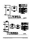
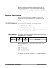
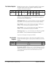
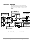

The Status Register Reading the register at base + 04
16
reads the amplifier’s Status register.
The Status register monitors the amplifier’s input/output enable
conditions and overload conditions.
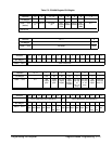
Address 15 14 13 - 12 11 10 9 8 7 - 0
base + 04
16
not used
(0)
MODID* not used
(0)
Main
Output
Ovld
Input 1
Enable
Input 2
Enable
Main
Output
State
FF
16
MODID. A zero (0) in bit 14 indicates that the amplifier is selected by a
high state on the P2 MODID line. A one (1) indicates the amplifier is
not selected via the P2 MODID line.
Main Output Ovld. A one (1) in bit 11 indicates an output signal (Main
Output BNC) can not be produced with the current input conditions.
Input 1 Enable. A one (1) in bit 10 indicates the ’Input 1’ BNC port is
enabled. A zero (0) indicates the input port is disabled.
Input 2 Enable. A one (1) in bit 9 indicates the ’Input 2’ BNC port is
enabled. A zero (0) indicates the input port is disabled.
Main Output State. A one (1) in bit 8 indicates the ’Main Output’ BNC
port is enabled. A zero (0) indicates the output port is disabled.
At power-on, the inputs and output are disabled.
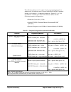
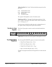
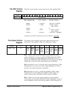
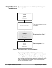
The Control
Register
Writing to the register at base + 04
16
writes to the amplifier’s Control
register. The Control register is used to perform a hardware reset of the
amplifier.
Address 15 - 1 0
base + 04
16
not used Reset
Resetting the Amplifier. Writing a one (1) to bit 0 (hardware) resets the
amplifier. Writing a zero (0) turns the reset function off. Bit 0 must be a
’1’ for at least 2
µs for the reset to occur. Bit 0 must be set to 0 for
normal operation.
C-8 Register-Based Programming Register Descriptions