


The DAC Control
Register
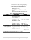
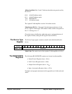
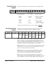
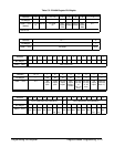
The DAC control register sets the output level of the amplifier/DAC.
Address 1514131211109876543210
base + 08
16
DAC Control Code
DAC Control Code DAC Output Amplifier Output
0000
16
+ full scale - full scale: -19.9992V
7FFE
16
+ 1 LSB - 1 LSB: -.610 µV
(open circuit)
7FFF
16
00
8000
16
- 1 LSB + 1 LSB: + .610 µV
(open circuit)
FFFF
16
- full scale + full scale: + 20.0000V
At power-on the DAC control code is set to 0, which is
- full scale.
The Output Control
Register
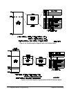
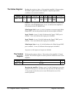
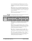
The Output Control register controls the output attenuation and
impedance of the amplifier’s ’Main’ and ’differential’ outputs.
Address 15 - 8 76543210
base + 0A
16
FF
16
0dB
output
path
20dB
output
path
50-75
Ω
output
imped.
’Main’
output
enable /
disable
50-75
Ω
out imp
of
non -inv
amp
50-75
Ω
out imp
of inv
amp
0
Ω
output
imped.
reserved
(must be
set to ’1’)
Bits 7 - 6. Bits 7 and 6 set the attenuation at the amplifiers’s main
output. Setting bit 7 to one (1) specifies the 0dB output path. Setting
bit 7 to zero (0) opens the 0dB output path. Setting bit 6 to one (1)
specifies the 20dB output path. Setting bit 6 to zero (0) opens the 20dB
output path. At power-on, the output attenuation is undefined.
Bit 5. Setting bit 5 to one (1) sets the ’Main’ output impedance to 50
Ω.
Setting bit 5 to zero (0) sets the ’Main’ output impedance to 75Ω. At
power-on, the output impedance is undefined.
Bit 4. Setting bit 4 to one (1) enables the amplifier’s ’Main’ output.
Setting bit 4 to zero (0) disables the amplifier’s ’Main’ output. At
power-on the bit value is undefined, but the output is disabled.
Bits 3 - 2. Bits 3 and 2 set the output impedance of the amplifier’s
non-inverting and inverting ’differential’ outputs. Setting bit 3 to one (1)
sets the impedance of the non-inverting output to 50
Ω. Setting bit 3 to
Register Descriptions Register-Based Programming C-9