Amplifier Block
Diagram
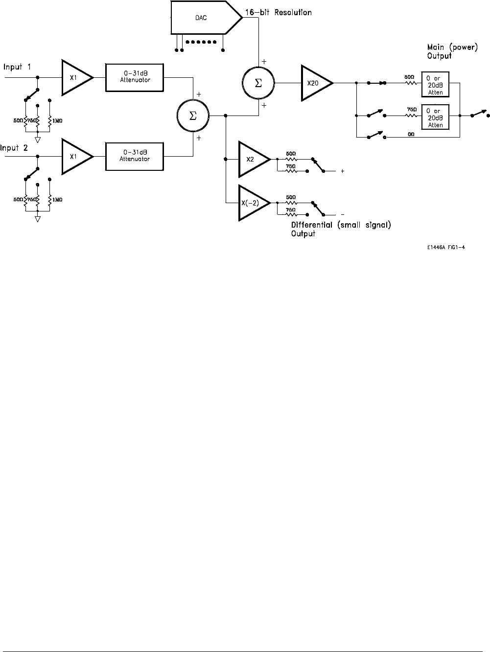
Figure 1-4 shows a block diagram of the Agilent E1446A Summing
Amplifier/DAC.
Input The Agilent E1446A Summing Amplifier/DAC has two input channels that
have identical input amplifiers with independently controlled input
impedance and input attenuation. The input amplifier attenuators provide
independent level control prior to the summing node. The attenuation can
range from 0 to 31 dB in 1 dB steps. The input impedance can be set to
50Ω, 75Ω, or 1 MΩ.
Output The output channels provide the amplifier with the capability to boost the
power output of a low-power signal source, and to provide low-level
differential output. The output channels are:
• single-ended main output or power amplifier.
• differential (small signal) output; one inverting, one non-inverting.
Main Output The power amplifier sums the two input channels plus the output of a 16-bit
offset Digital-to-Analog Converter (DAC) to obtain output levels of ±10
Vpeak into a 50Ω or 75
Ω load on the single-ended output or ±20 Vpeak
into high impedance. The voltage gain of the power amplifier is set at 10
(20 dB) into a matched load, and at 20 (about 26 dB) into a high impedance.
To obtain the desired output, the output attenuation and the output
impedance can be independently selected. The output impedance can be set
Figure 1-4. E1446A Summing Amplifier/DAC Block Diagram.
Basic Operation Getting Started 1-9


