


to 50Ω or 75Ω, or to 0Ω for driving into high impedance. The output
voltage can be attenuated by either 0 or 20 dB when 50Ω or 75Ω output
impedance is selected. Output attenuation is unavailable with the 0Ω mode
(high impedance).
The main output terminal may be enabled or disabled under user control.
When disabled, the output appears as an open circuit. This output is also
overload protected via an output relay. The output relay automatically opens
when an overload condition is detected and disconnects the output from the
load. An overload occurs if the sum of the inputs, plus the output of the
offset DAC, is excessive, or if the output current limit is reached. The relay
remains open until the overload condition is corrected and the output is reset
by the user. Refer to Appendix A of this manual for these specifications.
Differential (Small
Signal) Output
The differential (small signal) output sums the two input channels to obtain
a maximum output level of ±1 Vpeak into a 50/75Ω load. One of the
outputs is a non-inverting amplifier (same polarity as the input); whereas the
other is an inverting amplifier (opposite polarity as the input). Into a high
impedance, each input has a maximum gain of two. The output impedance
of each amplifier can be independently set to either 50Ω or 75Ω.
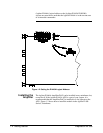
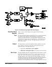
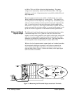
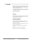
With two low level output terminals, output signals can be taken from either
of the terminals with respect to ground, or across the two terminals (in
series). Output signals taken across the two terminals will result in two
times the input voltage. Figure 1-5 shows the circuitry of the output signal
taken across the two terminals.
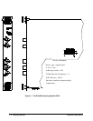
Figure 1-5. Measuring the Differential Output across both Terminals.
1-10 Getting Started Basic Operation