


1
CONTENTS
1. FUNCTIONS AND CONFIGURATION 1- 1 to 1-10
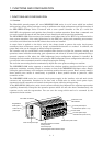
1.1 Overview...................................................................................................................................................1- 1
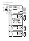
1.2 Function block diagram ..........................................................................................................................1- 2
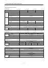
1.3 Unit standard specifications...................................................................................................................1- 3
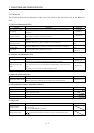
1.4 Function list .............................................................................................................................................1- 4
1.5 Model code definition ..............................................................................................................................1- 5
1.6 Combination with servo motor...............................................................................................................1- 6
1.7 Parts identification..................................................................................................................................1- 7
1.8 Servo system with auxiliary equipment................................................................................................1- 9
2. INSTALLATION AND START UP 2- 1 to 2-10
2.1 Environmental conditions.......................................................................................................................2- 1
2.2 Installation direction and clearances ....................................................................................................2- 2
2.3 Keep out foreign materials .....................................................................................................................2- 3
2.4 Cable stress ..............................................................................................................................................2- 3
2.5 Mounting method ....................................................................................................................................2- 4
2.6 When switching power on for the first time..........................................................................................2- 6
2.7 Start up.....................................................................................................................................................2- 7
2.8 Control axis selection ..............................................................................................................................2- 9
3. SIGNALS AND WIRING 3- 1 to 3-28
3.1 Connection example of control signal system.......................................................................................3- 2
3.2 I/O signals of interface unit ....................................................................................................................3- 4
3.2.1 Connectors and signal arrangements.............................................................................................3- 4
3.2.2 Signal explanations ..........................................................................................................................3- 5
3.2.3 Interfaces...........................................................................................................................................3- 6
3.3 Signals and wiring for extension IO unit..............................................................................................3- 9
3.3.1 Connection example .........................................................................................................................3- 9
3.3.2 Connectors and signal configurations ...........................................................................................3-11
3.3.3 Output signal explanations ............................................................................................................3-12
3.4 Signals and wiring for base unit ...........................................................................................................3-14
3.4.1 Connection example of power line circuit......................................................................................3-14
3.4.2 Connectors and signal configurations ...........................................................................................3-16
3.4.3 Terminals..........................................................................................................................................3-17
3.4.4 Power-on sequence...........................................................................................................................3-18
3.5 Connection of drive unit and servo motor............................................................................................3-19
3.5.1 Connection instructions ..................................................................................................................3-19
3.5.2 Connection diagram ........................................................................................................................3-19
3.5.3 I/O terminals ....................................................................................................................................3-20
3.6 Alarm occurrence timing chart .............................................................................................................3-21
3.7 Servo motor with electromagnetic brake .............................................................................................3-22
3.8 Grounding................................................................................................................................................3-26
3.9 Instructions for the 3M connector.........................................................................................................3-27