


5 - 19
5. PARAMETERS
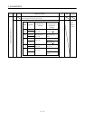
Classifi-
cation
No. Symbol Name and Function
Initial
Value
Unit
Setting
Range
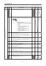
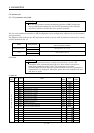
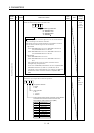
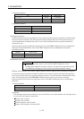
9 *SSC SSCNET type selection
Select the network type of the interface unit.
02
SSCNET type selection
00: SSCNET3.5ms
01: SSCNET1.7ms
02: SSCNET0.8ms
12: SSCNET
0200 Refer to
name
and
function
column.
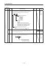
POINT
When using motion controller Q series, set the communication
cycle according to the motion controller.
The initial settings of communication cycle/number of control
axes of motion controller Q series are as follows:
1. Q173CPU
SV13: SSCNET0.8ms/1 to 8 axes, SSCNET1.7ms/9 to 16
axes, SSCNET3.5ms/17 to 32 axes
SV22: SSCNET0.8ms/1 to 4 axes, SSCNET1.7ms/5 to 12
axes, SSCNET3.5ms/13 to 32 axes
2. Q172CPU
SV13: SSCNET0.8ms/1 to 8 axes
SV22: SSCNET0.8ms/1 to 4 axes, SSCNET1.7ms/5 to 8
axes
The communication cycle of motion controller can be
changed using the parameter.
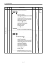
In the case of MR-J2M, initialization of servo amplifier MR-
J2M (LED indication "@ Ab#" or "@ AC#") will not be
completed, if the communication cycle settings are different
between the motion controller and servo amplifier MR-
J2M.
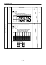
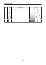
Basic IFU parameters
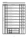
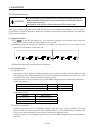
10 *OP2 Optional function 2
Choose the input signal filter and test operation.
0
Test operation selection
0: Invalid
1: Valid
Input signal filter
0: No
1: 1.777ms
2: 3.555ms
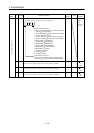
Electromagnetic brake interlock output axis number selection
Choose the axis number of the drive unit which uses
electromagnetic brake interlock output (MBR).
Setting Selected Axis
First axis
Second axis
Third axis
Fourth axis
Fifth axis
Sixth axis
Seventh axis
Eighth axis
All connected axes
0
1
2
3
4
5
6
7
8
0020 Refer to
name
and
function
column.