


2
4. OPERATION AND DISPLAY 4- 1 to 4-10
4.1 Normal indication....................................................................................................................................4- 1
4.1.1 Display sequence...............................................................................................................................4- 2
4.1.2 If alarm/warning occurs ...................................................................................................................4- 3
4.2 Status display mode of interface unit....................................................................................................4- 4
4.2.1 Display flowchart..............................................................................................................................4- 4
4.2.2 Status display of interface unit .......................................................................................................4- 5
4.2.3 Diagnostic mode of interface unit ...................................................................................................4- 6
4.2.4 Alarm mode of interface unit...........................................................................................................4- 7
4.2.5 Interface unit parameter mode .......................................................................................................4- 8
4.2.6 Output signal (DO) forced output ...................................................................................................4- 9
5. PARAMETERS 5- 1 to 5-26
5.1 Drive unit .................................................................................................................................................5- 1
5.1.1 Parameter write inhibit ...................................................................................................................5- 1
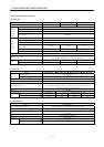
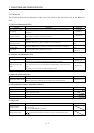
5.1.2 Lists....................................................................................................................................................5- 2
5.2 Interface unit ..........................................................................................................................................5-15
5.2.1 IFU parameter write inhibit...........................................................................................................5-15
5.2.2 Lists...................................................................................................................................................5-15
5.2.3 Analog monitor.................................................................................................................................5-21
5.2.4 Test operation mode ........................................................................................................................5-24
6. GENERAL GAIN ADJUSTMENT 6- 1 to 6-12
6.1 Different adjustment methods ...............................................................................................................6- 1
6.1.1 Adjustment on a MELSERVO-J2M................................................................................................6- 1
6.1.2 Adjustment using MR Configurator (servo configuration software)...........................................6- 3
6.2 Auto tuning ..............................................................................................................................................6- 4
6.2.1 Auto tuning mode .............................................................................................................................6- 4
6.2.2 Auto tuning mode operation............................................................................................................6- 5
6.2.3 Adjustment procedure by auto tuning............................................................................................6- 6
6.2.4 Response level setting in auto tuning mode ..................................................................................6- 7
6.3 Manual mode 1 (simple manual adjustment).......................................................................................6- 8
6.3.1 Operation of manual mode 1 ...........................................................................................................6- 8
6.3.2 Adjustment by manual mode 1 .......................................................................................................6- 8
6.4 Interpolation mode .................................................................................................................................6-11
7. SPECIAL ADJUSTMENT FUNCTIONS 7- 1 to 7-10
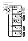
7.1 Function block diagram ..........................................................................................................................7- 1
7.2 Machine resonance suppression filter................................................................................................... 7- 1
7.3 Adaptive vibration suppression control................................................................................................. 7- 3
7.4 Low-pass filter .........................................................................................................................................7- 4
7.5 Gain changing function...........................................................................................................................7- 5
7.5.1 Applications ......................................................................................................................................7- 5
7.5.2 Function block diagram................................................................................................................... 7- 5
7.5.3 Parameters........................................................................................................................................7- 6
7.5.4 Gain changing operation .................................................................................................................7- 8
8. INSPECTION 8- 1 to 8- 2