


3
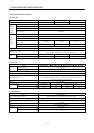
9. TROUBLESHOOTING 9- 1 to 9-10
9.1 Alarms and warning list .........................................................................................................................9- 1
9.2 Remedies for alarms................................................................................................................................9- 3
9.3 Remedies for warnings...........................................................................................................................9-10
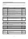
10. OUTLINE DRAWINGS 10- 1 to 10- 10
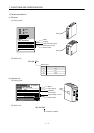
10.1 MELSERVO-J2M configuration example.........................................................................................10- 1
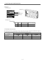
10.2 Unit outline drawings .........................................................................................................................10- 2
10.2.1 Base unit (MR-J2M-BU
)...........................................................................................................10- 2
10.2.2 Interface unit (MR-J2M-P8B) .....................................................................................................10- 2
10.2.3 Drive unit (MR-J2M-
DU)......................................................................................................... 10- 3
10.2.4 Extension IO unit (MR-J2M-D01) ..............................................................................................10- 4
10.2.5 Battery unit (MR-J2M-BT)..........................................................................................................10- 4
10.3 Connector .............................................................................................................................................10- 5
11. CHARACTERISTICS 11- 1 to 11- 6
11.1 Overload protection characteristics...................................................................................................11- 1
11.2 Power supply equipment capacity and generated loss ....................................................................11- 2
11.3 Dynamic brake characteristics...........................................................................................................11- 4
11.4 Encoder cable flexing life....................................................................................................................11- 6
12. OPTIONS AND AUXILIARY EQUIPMENT 12- 1 to 12-36
12.1 Options..................................................................................................................................................12- 1
12.1.1 Regenerative brake options .........................................................................................................12- 1
12.1.2 Cables and connectors..................................................................................................................12- 8
12.1.3 Maintenance junction card (MR-J2CN3TM) ............................................................................12-21
12.1.4 MR Configurator (servo configurations software)....................................................................12-23
12.2 Auxiliary equipment ..........................................................................................................................12-25
12.2.1 Recommended wires....................................................................................................................12-25
12.2.2 No-fuse breakers, fuses, magnetic contactors...........................................................................12-26
12.2.3 Power factor improving reactors................................................................................................12-27
12.2.4 Relays............................................................................................................................................12-28
12.2.5 Surge absorbers ...........................................................................................................................12-28
12.2.6 Noise reduction techniques.........................................................................................................12-28
12.2.7 Leakage current breaker ............................................................................................................12-34
12.2.8 EMC filter.....................................................................................................................................12-35
13. ABSOLUTE POSITION DETECTION SYSTEM 13- 1 to 13- 4
13.1 Features................................................................................................................................................13- 1
13.2 Specifications .......................................................................................................................................13- 2
13.3 Confirmation of absolute position detection data.............................................................................13- 3
APPENDIX App- 1 to App- 2
App 1. Status indication block diagram ................................................................................................. App- 1