


4 - 3
4. OPERATION AND DISPLAY
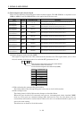
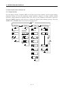
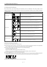
(1) Indication list
(Note 1) Indication Status Description
@ Ab# Initializing
MELSERVO-J2M was switched on when power to the servo system controller
is off.
@ AA# Initializing
Power to the servo system controller was switched off during power-on of
MELSERVO-J2M.
The axis No. set to the servo system controller does not match the axis No.
set with IFU parameter No.11 to No.18.
MELSERVO-J2M fault occurred or an error took place in communication
with the servo system controller. In this case, the indication changes:
"Ab"
"AC" "Ad" "Ab"
The servo system controller is faulty.
@ AC# Initializing
Communication started between the servo system controller and MELSERVO-
J2M.
@ Ad# Initializing The initial parameters from the servo system controller were received.
@ AE# Initialize completion Initial data communication with the servo system controller was completed.
@ b# Ready OFF The ready off signal from the servo system controller was received.
@ C# Servo OFF The ready off signal from the servo system controller was received.
@ d# Servo ON The ready off signal from the servo system controller was received.
(Note 2) @A**# Alarm Warning The alarm No./warning No. that occurred is displayed. (Refer to Section 9.1.)
@T b#.
@T c#.
@T d#.
(Note 3)
Test operation mode
It is a state of the test operation mode with the MR Configurator (servo
configuration software).
JOG operation, positioning operation, programmed operation, DO forced
output, motor-less operation.
Note 1. @ denotes the slot number of the base unit and # the axis number of the drive unit.
2. ** indicates the warning/alarm No.
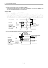
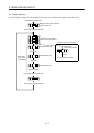
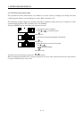
4.1.2 If alarm/warning occurs
(1) If alarm/warning occurs in drive unit
An alarm/warning which occurred in the drive unit is represented by the following indication.
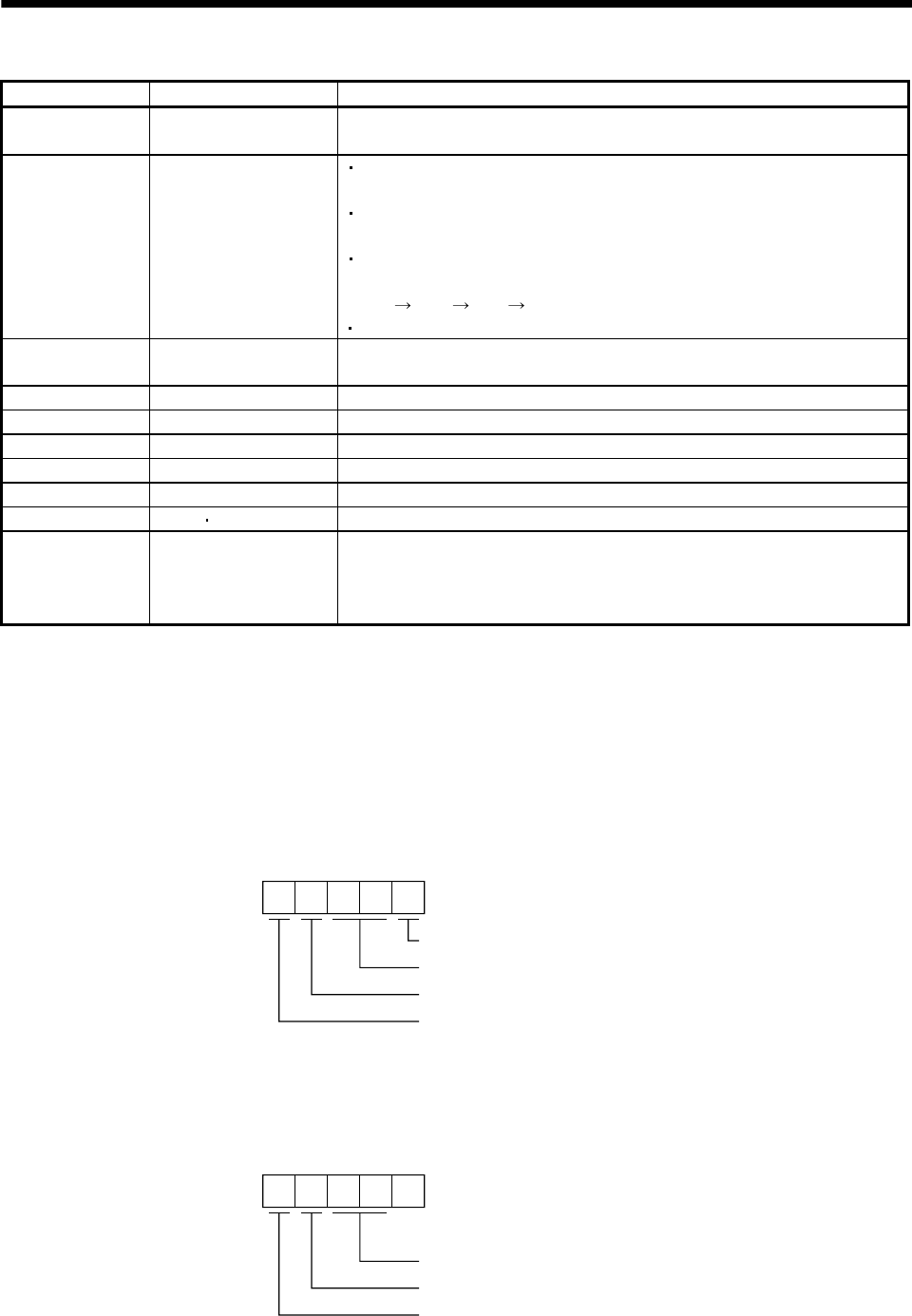
The following indication example assumes that an encoder error (A.16) occurred in the drive unit of
axis 3 installed on slot 1. During alarm occurrence, the decimal points in the fifth and second digits
flicker.
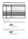
1. A 1 36.
Axis number
Alarm/warning number
Denotes alarm/warning indication.
Slot number
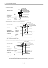
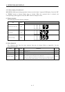
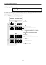
(2) If alarm/warning occurs in interface unit
An alarm/warning which occurred in the interface unit is represented by the following indication. The
following indication example assumes that interface unit undervoltage (A.10) occurred. During alarm
occurrence, the decimal points in the fifth and second digits flicker.
F. A 1 0.
Alarm/warning number
Denotes alarm/warning indication.
Denotes interface unit.