


3 - 9
3. SIGNALS AND WIRING
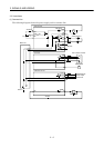
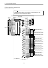
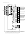
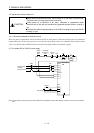
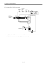
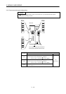
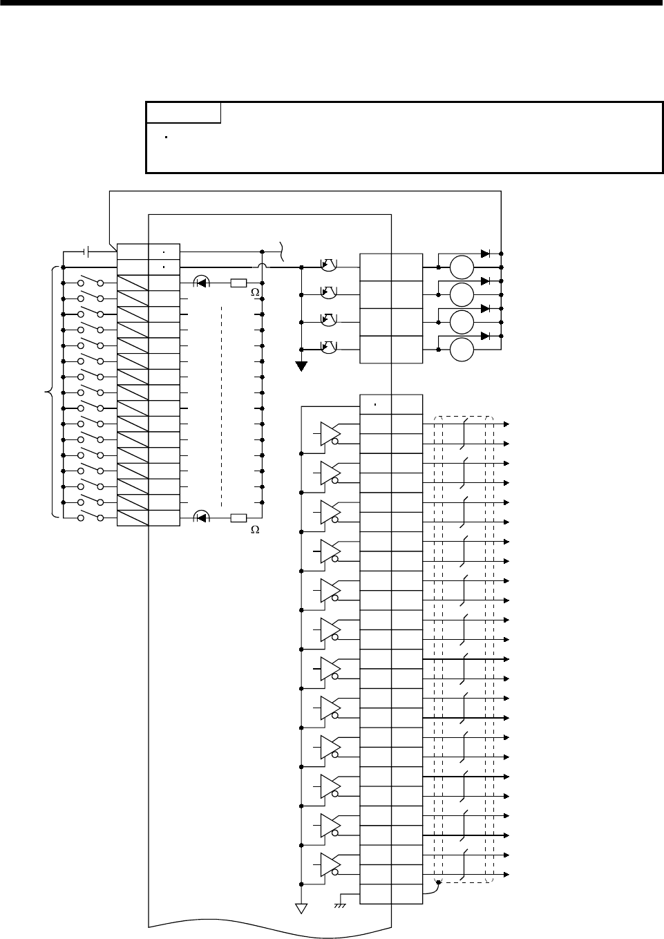
3.3 Signals and wiring for extension IO unit
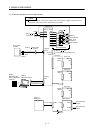
3.3.1 Connection example
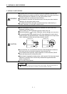
POINT
The pins without symbols can be assigned any devices using the MR
Configurator (servo configuration software).
RA2
RA4
RA19
10
34
35
MR-J2M-D01
RA3
LA1
LG
LAR1
LB1
LBR1
LZ1
LZR1
LA2
LAR2
LB2
LBR2
LZ2
LZR2
LA3
LAR3
LB3
LBR3
LZ3
LZR3
LA4
LAR4
LB4
LBR4
39 LZ4
14 LZR4
SD
SG
1
2
3
4
5
6
7
8
26
27
28
29
30
31
32
33
VIN
50
25
49
24
48
23
47
22
46
21
45
20
44
19
43
18
42
17
41
16
40
15
CN4B-11
(Note 3)
24VDC
(Note 2)
CN4A
11 36
12 37
Approx. 4.7k
Approx. 4.7k
(Note 2)
CN4A
(Note 1)
(Note 2)
CN4A
13 38
plate
Encoder A-phase pulse 1
(Differential line driver system)
Encoder B-phase pulse 1
(Differential line driver system)
Encoder Z-phase pulse 1
(Differential line driver system)
Encoder A-phase pulse 2
(Differential line driver system)
Encoder B-phase pulse 2
(Differential line driver system)
Encoder Z-phase pulse 2
(Differential line driver system)
Encoder A-phase pulse 3
(Differential line driver system)
Encoder B-phase pulse 3
(Differential line driver system)
Encoder Z-phase pulse 3
(Differential line driver system)
Encoder A-phase pulse 4
(Differential line driver system)
Encoder B-phase pulse 4
(Differential line driver system)
Encoder Z-phase pulse 4
(Differential line driver system)
(Note 4)
MBR1
MBR2
MBR3
MBR4