


3 - 3
3. SIGNALS AND WIRING
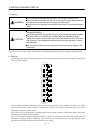
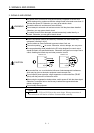
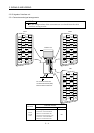
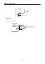
Note 1. To prevent an electric shock, always connect the protective earth (PE) terminal (terminal marked ) of the base unit to the
protective earth (PE) of the control box.
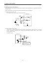
2. Connect the diode in the correct direction. If it is connected reversely, the interface unit will be faulty and will not output signals,
disabling the forced stop and other protective circuits.
3. If the controller does not have a forced stop function, always install a forced stop switch (Normally closed).
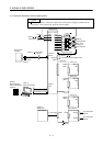
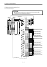
4. When a personal computer is connected for use of the test operation mode, always use the maintenance junction card (MR-
J2CN3TM) to enable the use of the forced stop (EM1). (Refer to section 12.1.5)
5. CN1A, CN1B, CN2 and CN3 have the same shape. Wrong connection of the connectors will lead to a fault.
6. When using the electromagnetic brake interlock (MBR) or forced stop (EM1), always supply 24VDC between VIN and SG.
7. When starting operation, always connect the forced stop (EM1) and SG. (Normally closed contacts) By setting “0001” in DRU
parameter No.23 of the drive unit, the forced stop (EM1) can be made invalid.
8. When connecting the personal computer together with analog monitor 1
2 3 use the maintenance junction card (MR-J2CN3TM).
(Refer to Section 12.1.3.)
9. Use MRZJW3-SETUP151E.
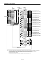
10. Use the bus cable at the overall distance of 30m(98.4ft) or less. In addition, to improve noise immunity, it is recommended to use a
cable clamp and data line filters (three or four filters connected in series) near the connector outlet.
11. Up to eight axes (n
1 to 8) may be connected. The MR-J2S- B/MR-J2-03B5 servo amplifier may be connected on the same
bus.
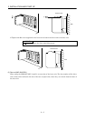
12. Always insert the termination connector (MR-A-TM) into CN1B of the interface unit located at the termination.
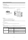
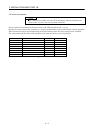
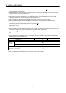
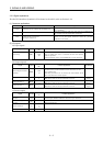
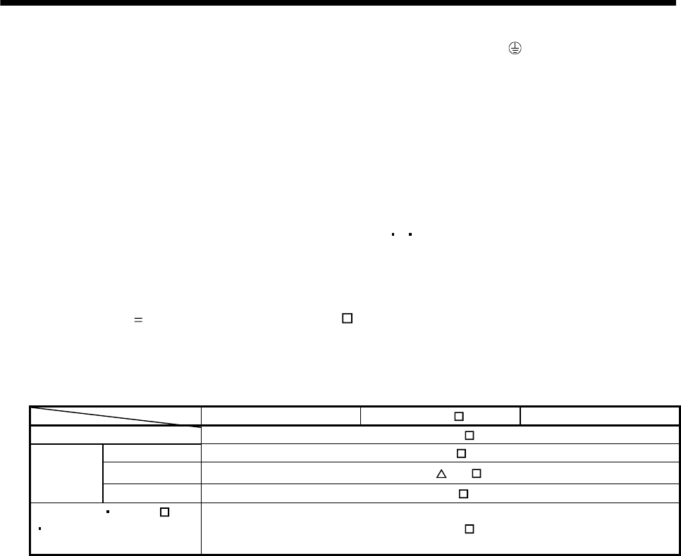
13. The bus cable used with the SSCNET depends on the preceding or subsequent controller or servo amplifier connected. Refer to
the following table and choose the bus cable.
MR-J2M-P8B MR-J2S-
B MR-J2-03B5
QD75M MR-J2HBUS M
Q172CPU(N) Q172J2BCBL M(-B)
Q173CPU(N) Q173J2B CBL M
Motion
controller
A motion MR-J2HBUS
M-A
MR-J2M-P8B MR-J2S- B
MR-J2-03B5
Maintenance junction card
MR-J2HBUS M
14. When using an absolute position detection system, connect the battery unit (MR-J2M-BT).