3 - 24
3. SIGNALS AND WIRING
(b) Electromagnetic brake interlock 1 to 8 (MBR1 to MBR8)
By adding an extension IO unit, you can use the electromagnetic brake interlock (MBR) for each
axis. The timing chart is as shown in (4) of this section.
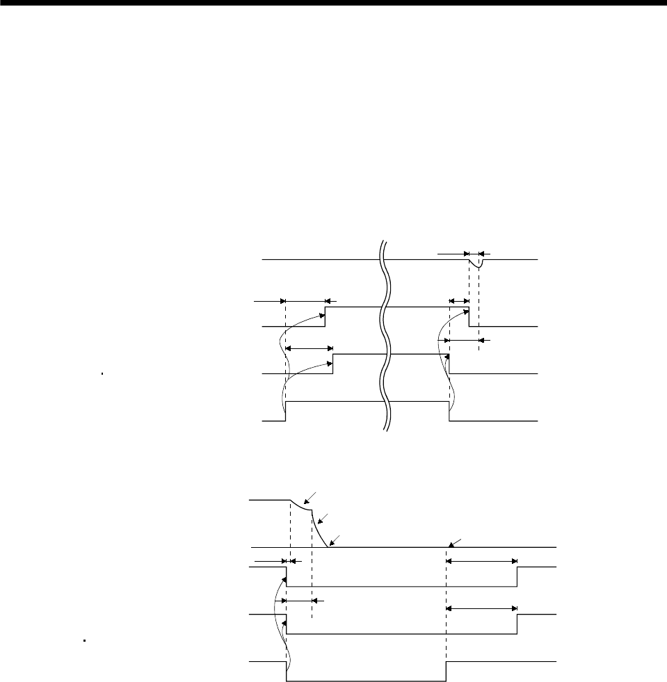
(4) Timing charts
(a) Servo-on command (from controller) ON/OFF
Delay time (Tb) [ms] after the servo-on is switched off, the servo lock is released and the servo
motor coasts. If the electromagnetic brake is made valid in the servo lock status, the brake life may
be shorter. Therefore, when using the electromagnetic brake in a vertical lift application or the
like, set Tb to about the same as the electromagnetic brake operation delay time to prevent a drop.
(100ms)
(120ms)
Tb
ON
OFF
0 r/min
ON
OFF
Servo motor speed
Base circuit
Servo-on command
(from controller)
Invalid(ON)
Valid(OFF)
Coasting
Electromagnetic brake
operation delay time
Electromagnetic
brake interlock
(MBR MBR1 to MBR8)
(b) Forced stop command (from controller) or forced stop (EM1) ON/OFF
ON
OFF
(10ms)
(180ms)
(180ms)
Servo motor speed
Base circuit
Invalid (ON)
Valid (OFF)
Forced stop
command(from controller)
or
Fo
r
ced stop (EM1)
Dynamic brake
Dynamic brake
Electromagnetic brake
Electromagnetic brake
Invalid (ON)
Valid (OFF)
Electromagnetic brake
operation delay time
Electromagnetic brake release
Electromagnetic
brake interlock
(MBR MBR1 to MBR8)


