


3 - 2
3. SIGNALS AND WIRING
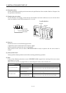
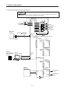
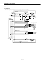
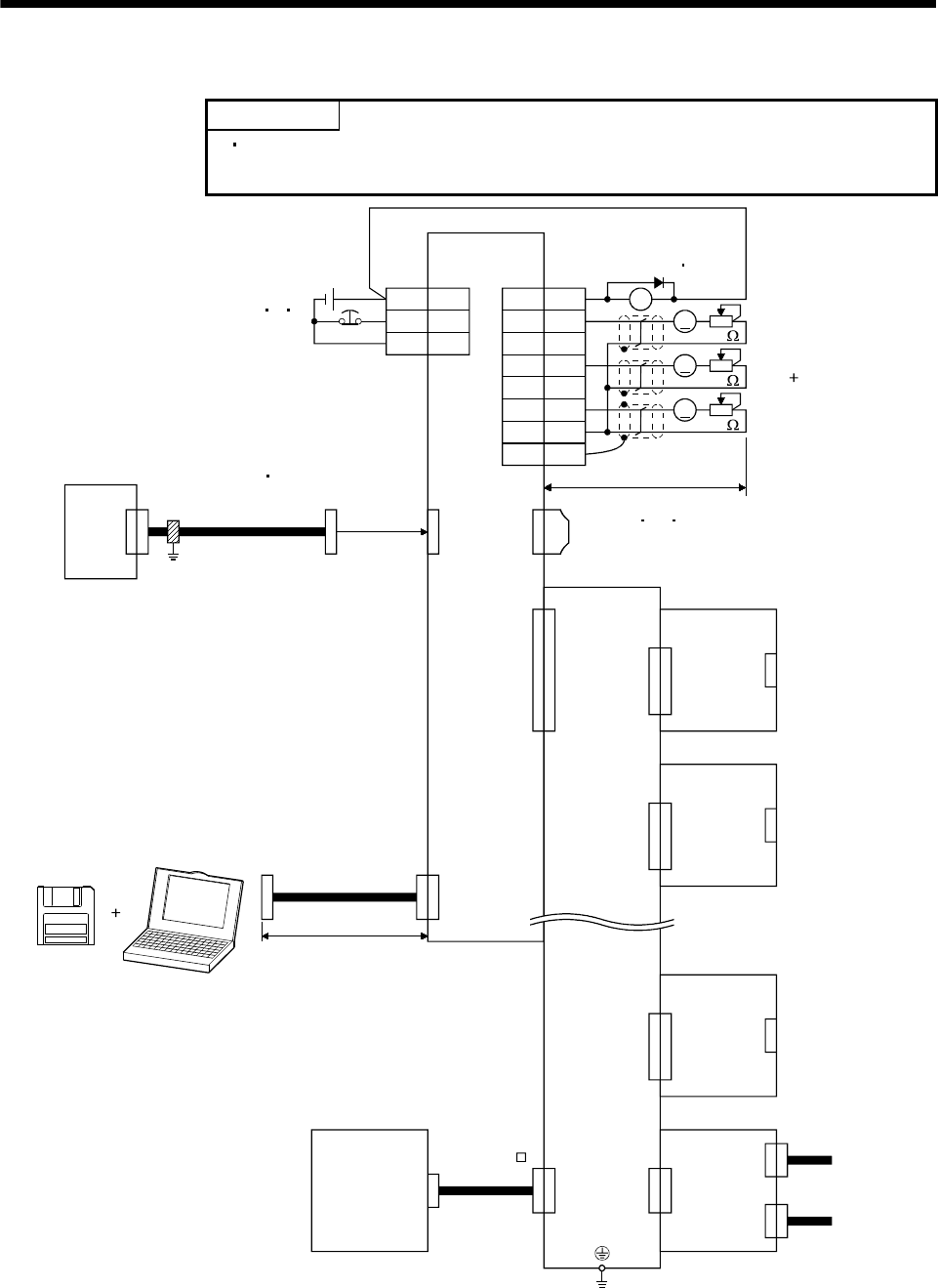
3.1 Connection example of control signal system
POINT
Refer to Section 3.4 for the connection of the power supply system and to
Section 3.5 for connection with the servo motor.
EM1 20
A
4MO1
14 MO2
7MO3
11 LG
SD
8
VIN
A
A
CON4CON5
MR-J2M-BT
SG 3
13 MBR
RA
CN3 CN3
CN2
CN4A
CN4B
Interface unit
(Note 5) (Note 5)
(Note 3 4 7)
Forced stop
Servo system
controller
Bus cable
(Option)
(Note 10 13)
Cable clamp
(Option)
(Note 9)
MR Configurator
(servo configuration
software)
(Note 4)
Personal computer
15m(49.2ft) or less
(Note 5)
CN3
(Note 5)
CN1A
(Note 5)
CN1B
Plate
(Note 2 6)
10k
10k
10k
2m(6.56ft) or less
(Note 8)
Analog monitor
Max. 1mA
Reading in
both directions
(Note 11 12 13)
Termination connector (MR-A-TM)
Base unit
(Slot 1)
(Note 5)
CN2
(Note 5)
Drive unit
Drive unit
(Slot 2)
Drive unit
CN2
(Note 5)
(Slot 8)
MR-J2M-D01
Encoder output
pulses
Encoder output
pulses
(Note 1)
Battery unit
(Note 14)
MR-J2MBTCBL M
24VDC
CON3A
CON3B
CON3H