


5 - 17
5. PARAMETERS
Classifi-
cation
No. Symbol Name and Function
Initial
Value
Unit
Setting
Range
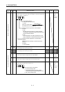
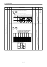
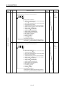
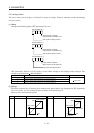
3 *MD1 Analog monitor 1 output
Choose the signal to be output to analog monitor 1.
00
Analog monitor 1 selection
0: Servo motor speed ( 4V/max. Servo motor speed)
1: Torque ( 4V/max. Torque)
2: Servo motor speed ( 4V/max. Servo motor speed)
3: Torque ( 4V/max. Torque)
4: Current command ( 4V/max. Current command)
5: Speed command ( 4V/max. Servo motor speed)
6: Droop pulses ( 4V/128pulse)
7: Droop pulses ( 4V/2048pulse)
8: Droop pulses ( 4V/8192pulse)
9: Droop pulses ( 4V/32768pulse)
A: Droop pulses ( 4V/131072pulse)
B: Bus voltage ( 4V/400V)
C: In position ( 4V/ON)
D: Ready ( 4V/ON)
E: Trouble ( 4V/ON)
Axis number of channel 1
Choose the axis number output to analog monitor 1.
Axis number set value. Selecting 0 disables output.
0000 Refer to
name
and
function
column.
Basic IFU parameters
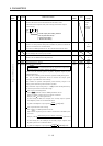
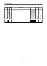
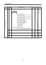
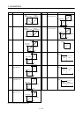
4 *MD2 Analog monitor 2 output
Choose the signal to be output to analog monitor 2.
00
Analog monitor 2 selection
0: Servo motor speed ( 4V/max. Servo motor speed)
1: Torque ( 4V/max. Torque)
2: Servo motor speed ( 4V/max. Servo motor speed)
3: Torque ( 4V/max. Torque)
4: Current command ( 4V/max. Current command)
5: Speed command ( 4V/max. Servo motor speed)
6: Droop pulses ( 4V/128pulse)
7: Droop pulses ( 4V/2048pulse)
8: Droop pulses ( 4V/8192pulse)
9: Droop pulses ( 4V/32768pulse)
A: Droop pulses ( 4V/131072pulse)
B: Bus voltage ( 4V/400V)
C: In position ( 4V/ON)
D: Ready ( 4V/ON)
E: Trouble ( 4V/ON)
Axis number of channel 2
Choose the axis number output to analog monitor 2.
Axis number set value. Selecting 0 disables output.
0000 Refer to
name
and
function
column.