


12 - 25
12. OPTIONS AND AUXILIARY EQUIPMENT
12.2 Auxiliary equipment
Always use the devices indicated in this section or equivalent. To comply with the EN Standard or UL/C-
UL(CSA) Standard, use the products which conform to the corresponding standard.
12.2.1 Recommended wires
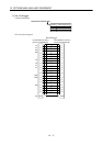
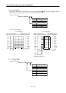
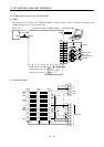
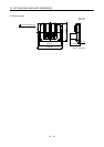
(1) Wires for power supply wiring
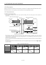
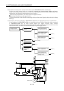
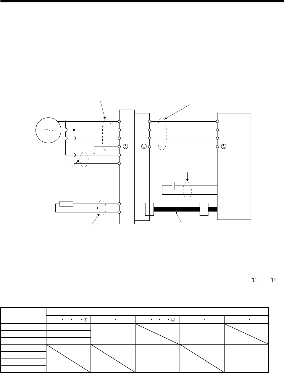
The following diagram shows the wires used for wiring. Use the wires given in this section or
equivalent.
C
P
U
V
W
L
11
L21
B1
B2
U
V
W
L
1
L
2
L
3
CN2
1) Main circuit power supply lead
Power supply
3) Motor power supply lead
Servo motor
Encoder cable (refer to Section 12.1.2)
4) Regenerative brake option lead
5) Electromagnetic
brake lead
2) Control circuit power supply lead
Regenerative brake option
Motor
Electro-
magnetic
brake
Encoder
Base unit
Drive unit
(Earth)
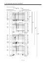
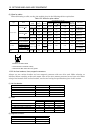
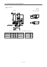
The following table lists wire sizes. The wires used assume that they are 600V vinyl wires and the
wiring distance is 30m(98.4ft) max. If the wiring distance is over 30m(98.4ft), choose the wire size in
consideration of voltage drop.
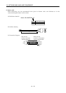
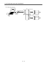
The servo motor side connection method depends on the type and capacity of the servo motor. Refer to
Section 3.5.3.
To comply with the UL/C-UL (CSA) Standard, use UL-recognized copper wires rated at 60
(140 ) or
more for wiring.
Table 12.1 Recommended wires
Wires [mm
2
]
Unit
1) L
1 L2 L3 2) L11 L21 3) U V W 4) P C5) B1B2
MR-J2M-BU4 2 (AWG14)
MR-J2M-BU6 3.5 (AWG12)
MR-J2M-BU8 5.5 (AWG10)
2 (AWG14) 2 (AWG14)
MR-J2M-10DU
MR-J2M-20DU
MR-J2M-40DU
MR-J2M-70DU
1.25 (AWG16)
1.25 (AWG16)