


3 - 17
3. SIGNALS AND WIRING
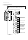
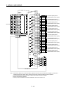
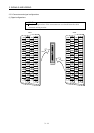
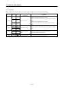
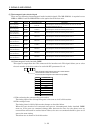
3.4.3 Terminals
Refer to Section 10.2.1 for the layouts and signal configurations of the terminal blocks.
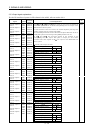
Connector Pin No. Code
Connection target
(Application)
Description
1L
1
2L
2
CNP3
3L
3
Main circuit power
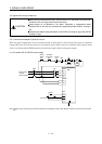
(1) When using a three-phase power supply
Supply L
1, L2 and L3 with three-phase, 200 to 230VAC, 50/60Hz
power.
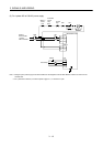
(2) When using a signal-phase power supply
Supply L
1 and L2 with signal-phase, 200 to 230VAC, 50/60Hz
power.
1L
11
2L
21
CNP1B
3
Control circuit power
Supply L
11
and L
21
with single-phase, 200 to 230VAC, 50/60Hz
power.
1N
2P
CNP1A
3C
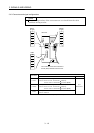
Regenerative brake
option
Connect the regenerative brake option across P-C.
Keep N open. (Refer to Section 12.1.1)
Protective earth (PE)
Connect this terminal to the protective earth (PE) terminals of the
servo motor and control box for grounding.