


12 - 8
12. OPTIONS AND AUXILIARY EQUIPMENT
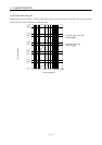
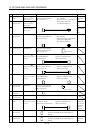
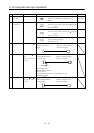
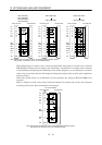
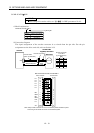
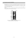
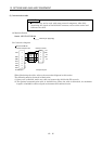
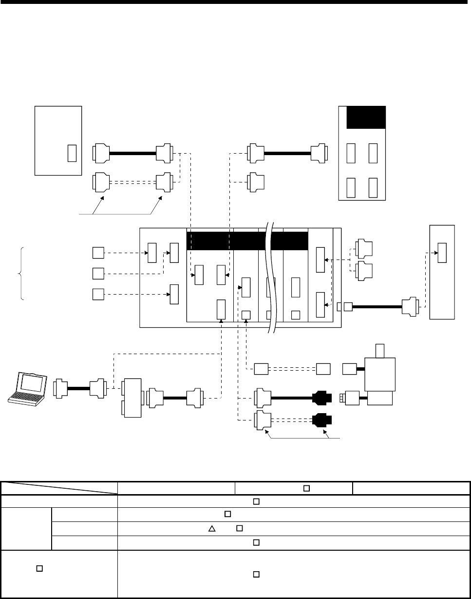
12.1.2 Cables and connectors
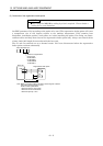
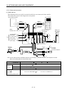
(1) Cable make-up
The following cables are used for connection with the servo motor and other models.
The broken line areas in the diagram are not options.
HC-KFS
HC-MFS
HC-UFS 3000r/min
4)
(Note)
12)
CNP3
CN1A CN1B
CN3
CN2
CNP2
CN2
CNP2
13) 14)15)
BU IFU DRUDRU
CON5
17)
CN1C
Servo system controller
(Note)
Bus cable
(Note)
Bus cable
or 10)
Termination
connector
Servo amplifier
CN1ACN1B
CN2 CN3
(Note)
Connector set
To regenerative
brake option
To control circuit
power supply
To main circuit
power supply
16)
Extension IO unit
MR-J2M-D01
CNP1A CNP1B
Battery unit
MR-J2M-BT
Personal
computer
11)
1) 2) 3)
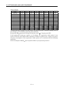
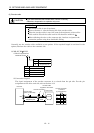
Note. The bus cable used with the SSCNET depends on the preceding or subsequent controller or servo amplifier connected.
Refer to the following table and choose the bus cable.
CN4A
CN4B
5)
MR-J2M-P8B MR-J2S-
B MR-J2-03B5
QD75M 7) Bus cable :MR-J2HBUS M 9) Connector set:MR-J2CN1
Q172CPU(N) 18) Bus cable :Q172J2BCBL M(-B)
Q173CPU(N) 19) Bus cable :Q173J2B CBL M
Motion
controller
A motion 6) Bus cable :MR-J2HBUS
M-A 8) Connector set:MR-J2CN1-A
MR-J2M-P8B
MR-J2S-
B
MR-J2-03B5
Maintenance junction card
7) Bus cable :MR-J2HBUS
M 9) Connector set:MR-J2CN1