


3 - 10
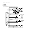
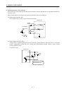
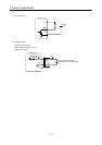
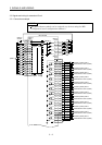
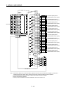
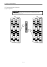
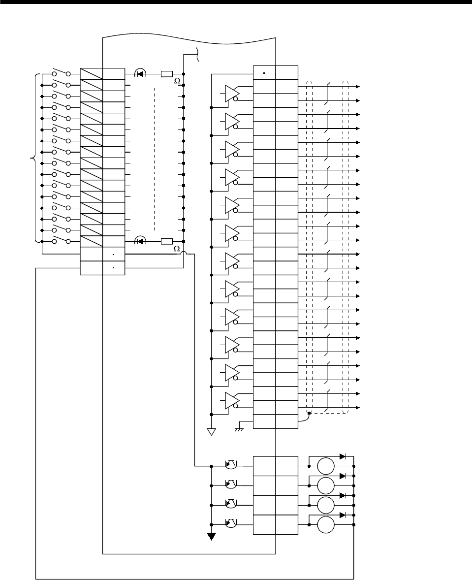
3. SIGNALS AND WIRING
RA8
RA10
RA7
9
10
34
35
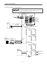
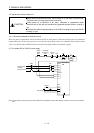
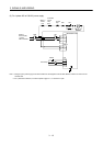
MR-J2M-D01
RA9
50 LA5
LG
25 LAR5
49 LB5
24 LBR5
48 LZ5
23 LZR5
47 LA6
22 LAR6
46 LB6
21 LBR6
45 LZ6
20 LZR6
44 LA7
19 LAR7
43 LB7
18 LBR7
42 LZ7
17 LZR7
41 LA8
16 LAR8
40 LB8
15 LBR8
39 LZ8
14 LZR8
SD
1
2
3
4
5
6
7
8
26
27
28
29
30
31
32
33
SG
VIN
CN4A-11
(Note 2)
CN4B
(Note 2)
CN4B
plate
Encoder A-phase pulse 5
(Differential line driver system)
Approx. 4.7k
Approx. 4.7k
12 37
11 36
(Note 2)
CN4B
(Note 1)
Encoder B-phase pulse 5
(Differential line driver system)
Encoder Z-phase pulse 5
(Differential line driver system)
Encoder A-phase pulse 6
(Differential line driver system)
Encoder B-phase pulse 6
(Differential line driver system)
Encoder Z-phase pulse 6
(Differential line driver system)
Encoder A-phase pulse 7
(Differential line driver system)
Encoder B-phase pulse 7
(Differential line driver system)
Encoder Z-phase pulse 7
(Differential line driver system)
Encoder A-phase pulse 8
(Differential line driver system)
Encoder B-phase pulse 8
(Differential line driver system)
Encoder Z-phase pulse 8
(Differential line driver system)
Note 1. Connect the diodes in the correct orientation. Opposite connection may cause the servo amplifier to be faulty and
disable the signals from being output, making the forced stop and other protective circuits inoperative.
2. The signals having the same name are connected to the inside of the servo amplifier.
3. Always connect 24VDC (200mA).
4. These pins are unavailable when the MR-J2M-P8B is used as the interface unit.
13 38
(Note 4)
MBR5
MBR6
MBR7
MBR8