


3 - 20
3. SIGNALS AND WIRING
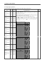
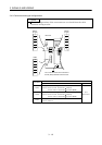
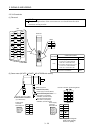
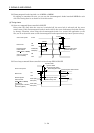
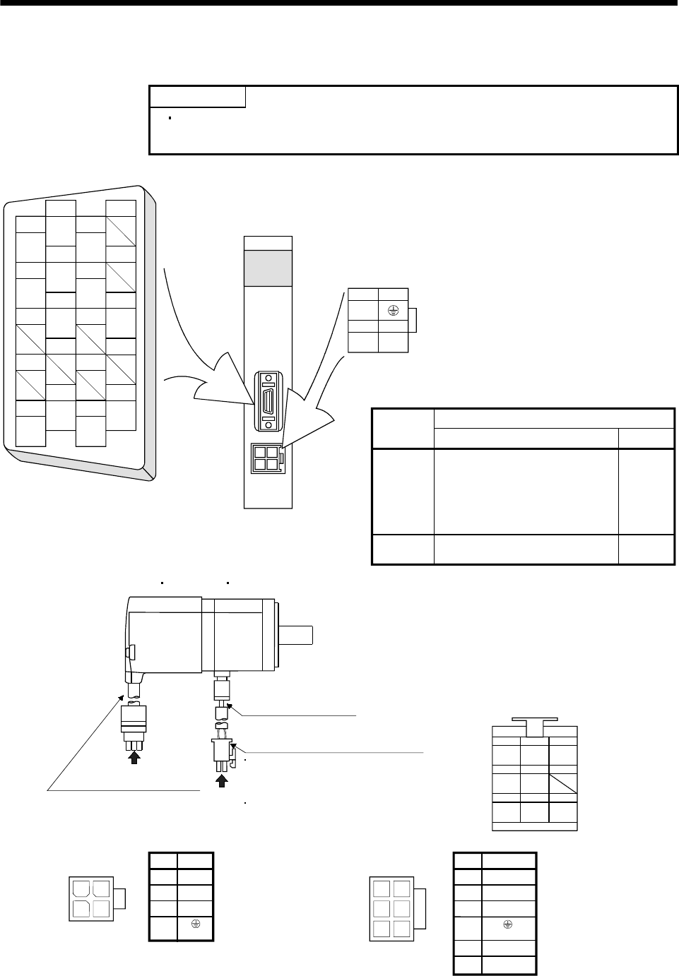
3.5.3 I/O terminals
(1) Drive unit
POINT
The pin configurations of the connectors are as viewed from the cable
connector wiring section.
19
P5
20
P5
10
9
BAT
17
MRR
18
P5
8
7
MR
15
LG
16
MDR
6
MD
5
13
14 4
3
11
12
LG
2
1
LG
24
13
V
UW
CNP2
CN2
3M
Molex
LG
CNP2
CN2
Drive unit
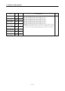
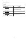
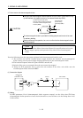
Connector
Cable side connector
Model Maker
1. Soldering type
Connector: 10120-3000VE
Shell kit: 10320-52F0-008
2. Insulation displacement type
Connector: 10120-6000EL
Shell kit: 10320-3210-000
Housing: 5557-04R-210
Terminal: 5556PBT3L
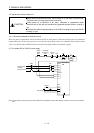
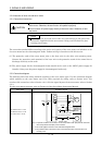
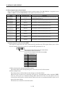
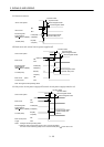
(2) Servo motor (HC-KFS HC-MFS HC-UFS3000r/min series)
24
13
4
Power supply connector (Molex)
Without electromagnetic brake
5557-04R-210 (receptacle)
5556PBTL (Female terminal)
With electromagnetic brake
5557-06R-210 (receptacle)
5556PBTL (Female terminal)
Encoder cable 0.3m (0.98ft.)
Power supply lead
4-AWG19 0.3m (0.98ft.)
With connector 1-172169-9
(Tyco Electronics)
1
2
3
4
1
25
4
36
1
2
3
5
6
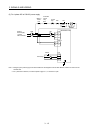
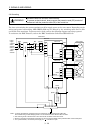
Power supply
connector
5557-04R-210
Pin
Signal
(Earth)
U
V
W
Power supply
connector
5557-06R-210
Pin
Signal
(Earth)
U
V
W
MR
123
MRR BAT
MD
456
MDR
P5
789
LG SHD
Encoder connector signal arrangement
B1
B2
(Note)
(Note)
Note. Supply electromagnetic
brake power (24VDC).
There is no polarity.
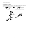
a
b
View b
View b
View a