


3 - 19
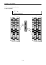
3. SIGNALS AND WIRING
3.5 Connection of drive unit and servo motor
3.5.1 Connection instructions
CAUTION
Connect the wires to the correct phase terminals (U, V, W) of the drive unit and
servo motor. Otherwise, the servo motor will operate improperly.
Do not connect AC power supply directly to the servo motor. Otherwise, a fault
may occur.
POINT
Do not apply the test lead bars or like of a tester directly to the pins of the
connectors supplied with the servo motor. Doing so will deform the pins,
causing poor contact.
The connection method differs according to the series and capacity of the servo motor and whether or not
the servo motor has the electromagnetic brake. Perform wiring in accordance with this section.
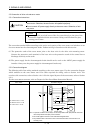
(1) The protective earth of the servo motor joins to the base unit via the drive unit mounting screw.
Connect the protective earth terminal of the base unit to the protective earth of the control box to
discharge electricity to the earth.
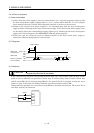
(2) The power supply for the electromagnetic brake should not be used as the 24VDC power supply for
interface. Always use the power supply for electromagnetic brake only.
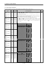
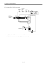
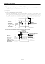
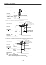
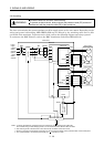
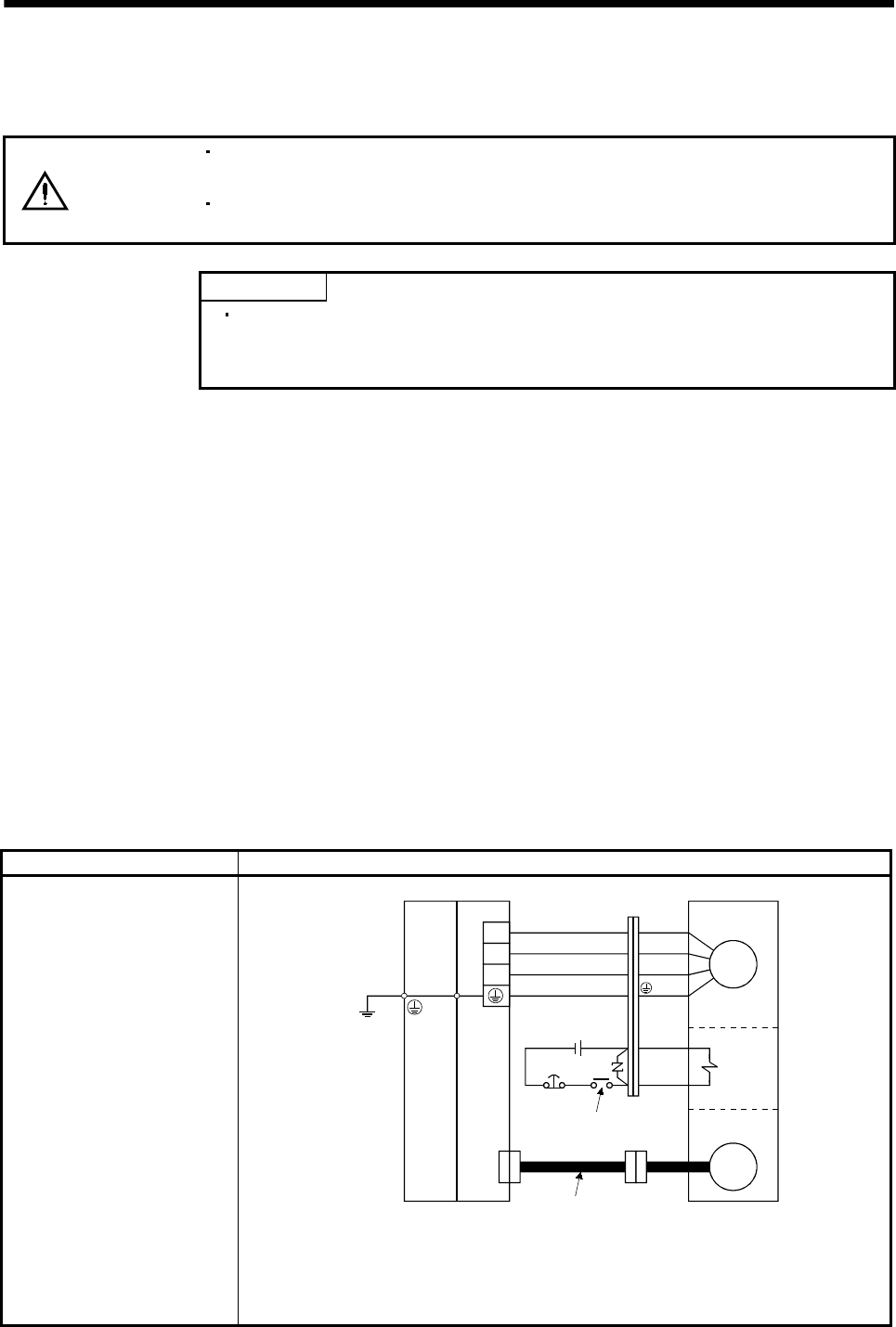
3.5.2 Connection diagram
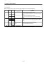
The following table lists wiring methods according to the servo motor types. Use the connection diagram
which conforms to the servo motor used. For cables required for wiring, refer to Section 12.2.1. For
encoder cable connection, refer to Section 12.1.2. For the signal layouts of the connectors, refer to Section
3.5.3.
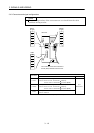
For the servo motor connector, refer to Chapter 3 of the Servo Motor Instruction Manual.
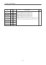
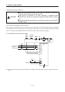
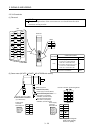
Servo motor Connection diagram
HC-KFS053 (B) to 73 (B)
HC-MFS053 (B) to 73 (B)
HC-UFS13 (B) to 73 (B)
U
V
W
EM1
B1
B2
CNP2
CN2
24VDC
(Note 1)
Encoder
Electro-
magnetic
brake
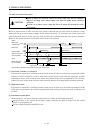
To be shut off when servo-
off or alarm occurrence
Encoder cable
Motor
Servo motor
(Note 2)
(Note 3)
U (Red)
V (White)
W (Black)
(Green)
Base unit Drive unit
Note 1. To prevent an electric shock, always connect the protective earth (PE) terminal of the base
unit to the protective earth (PE) of the control box.
2. This circuit applies to the servo motor with electromagnetic brake.
3. The protective earth of the servo motor is connected to the base unit via the drive unit
mounting screw.