


3 - 13
3. SIGNALS AND WIRING
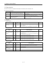
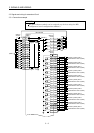
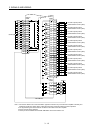
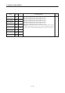
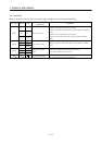
Signal Symbol
Connector
pin No.
Function/Applications
I/O
division
Electromagnetic
brake interlock 1
MBR1 CN4A-9
Electromagnetic
brake interlock 2
MBR2 CN4A-10
Electromagnetic
brake interlock 3
MBR3 CN4A-34
Electromagnetic
brake interlock 4
MBR4 CN4A-35
Electromagnetic
brake interlock 5
MBR5 CN4A-9
Electromagnetic
brake interlock 6
MBR6 CN4A-10
Electromagnetic
brake interlock 7
MBR7 CN4A-34
Electromagnetic
brake interlock 8
MBR8 CN4A-35
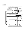
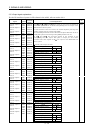
MBR1: Electromagnetic brake interlock signal for axis 1
MBR2: Electromagnetic brake interlock signal for axis 2
MBR3: Electromagnetic brake interlock signal for axis 3
MBR4: Electromagnetic brake interlock signal for axis 4
MBR5: Electromagnetic brake interlock signal for axis 5
MBR6: Electromagnetic brake interlock signal for axis 6
MBR7: Electromagnetic brake interlock signal for axis 7
MBR8: Electromagnetic brake interlock signal for axis 8
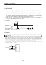
MBR
-SG are disconnected when a forced stop is made valid, an alarm
occurs in the interface unit or drive unit, or the servo switches off. At alarm
occurrence, they are disconnected independently of the base circuit status.
DO-1