


2 - 9
2. INSTALLATION AND START UP
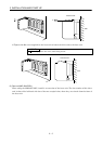
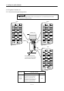
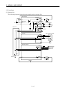
2.8 Control axis selection
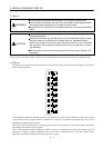
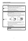
POINT
The control axis number set to the IFU parameter software should be the
same as the one set to the servo system controller.
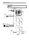
Set the control axis numbers of the drive units in the IFU parameters No. 11 to 18.
Setting the same control axis numbers in a single communication system will disable normal operation.
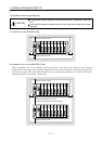
Each control axis can be set independently of the slot number where the drive unit has been installed.
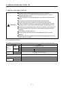
The axis numbers of the drive units installed to the slots are factory-set as listed below.
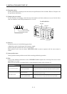
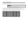
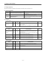
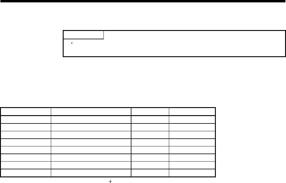
IFU Parameter No. Name Initial Value (Note) Definition
11 1 slot axis number selection 0000 Axis 1
12 2 slot axis number selection 0001 Axis 2
13 3 slot axis number selection 0002 Axis 3
14 4 slot axis number selection 0003 Axis 4
15 5 slot axis number selection 0004 Axis 5
16 6 slot axis number selection 0005 Axis 6
17 7 slot axis number selection 0006 Axis 7
18 8 slot axis number selection 0007 Axis 8
Note. The axis number is represented as a set value 1.