


4 - 5
4. OPERATION AND DISPLAY
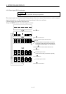
4.2.2 Status display of interface unit
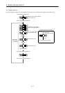
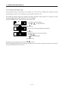
MELSERVO-J2M status during operation is shown on the 5-digit, 7-segment LED display. Press the "UP"
or "DOWN" button to change display data as desired. When the required data is selected, the
corresponding symbol appears. Press the "SET" button to display its data.
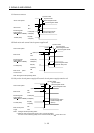
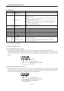
(1) Display examples
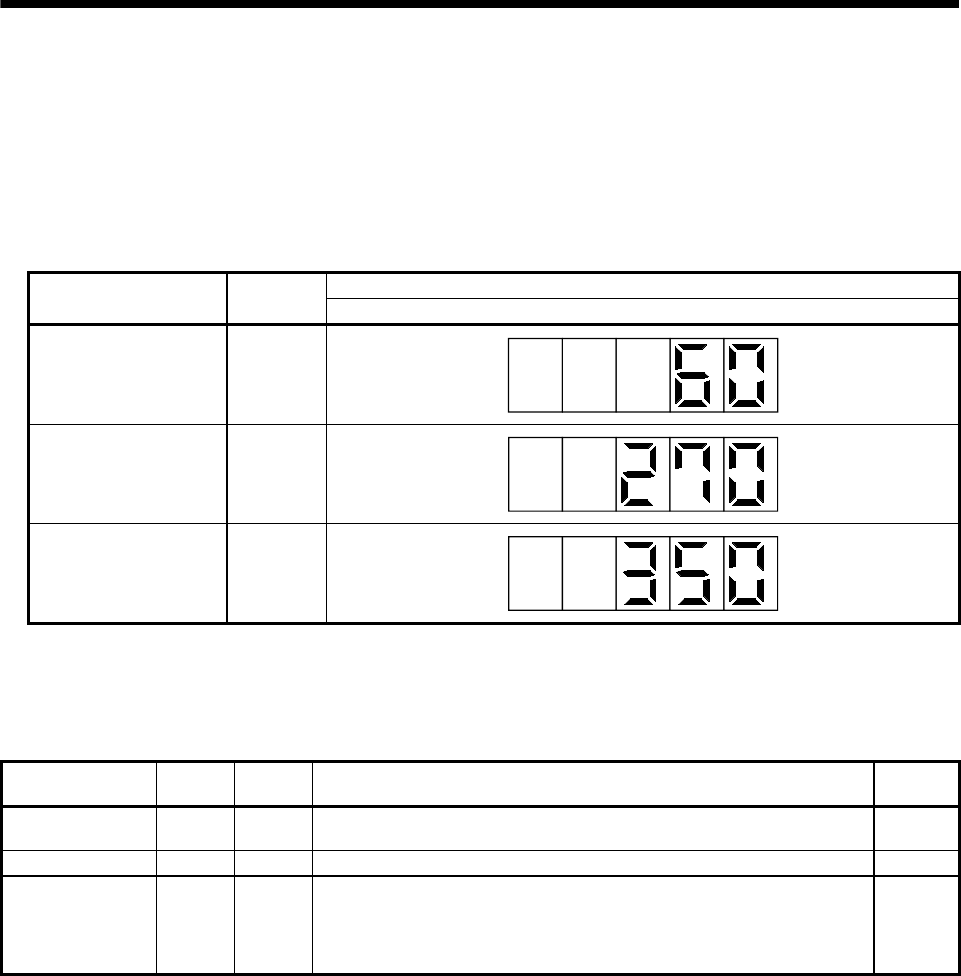
The following table lists display examples:
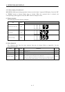
Displayed data
Item Status
Interface unit display
Regenerative load ratio 60%
Bus voltage 270V
Peak bus voltage 350V
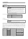
(2) Status display list
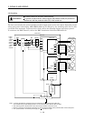
The following table lists the servo statuses that may be shown: Refer to Appendix 1 for the
measurement point.
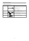
Name Symbol Unit Description
Display
range
Regenerative load
ratio
L%
The ratio of regenerative power to permissible regenerative power is
displayed in %.
0 to 100
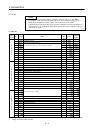
Bus voltage Pn V The voltage (across P-N) of the main circuit converter is displayed. 0 to 450
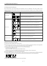
Peak bus voltage PnP V
Shows the maximum voltage of the main circuit converter (across P-N).
The maximum value during past 15s is displayed.
If there is a difference of 40V or more between the bus voltage and peak
bus voltage during normal operation, use the regenerative brake option.
0 to 450