


3 - 23
3. SIGNALS AND WIRING
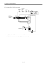
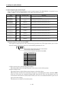
(3) Electromagnetic brake interlock signal
There are the following electromagnetic brake interlock signals. The MR-J2M-D01 is required to use
MBR1 to MBR8. Load the MR-J2M-D01 to the option slot of the base unit.
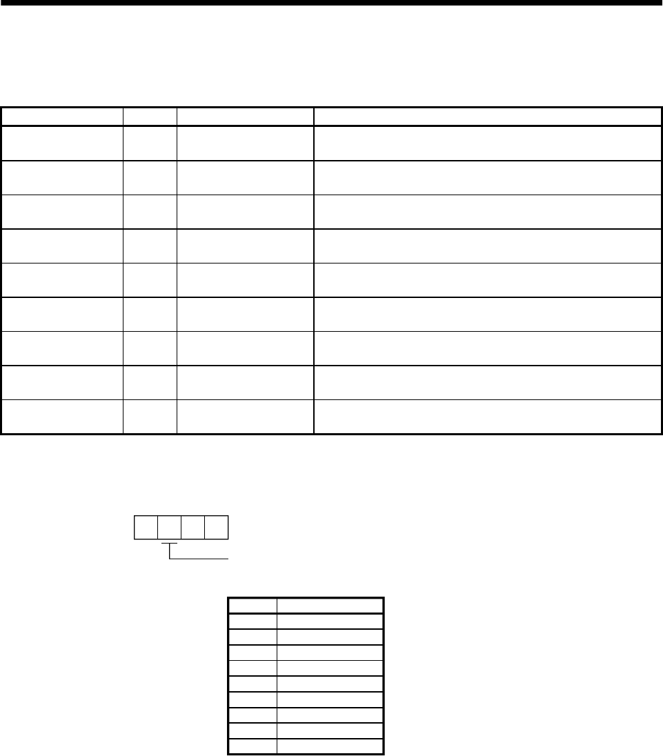
Signal Symbol Connector Pin No. Description
Electromagnetic
brake interlock
MBR CN3-13
Electromagnetic brake interlock signal for all axes or the axis
selected in parameter No. 10
Electromagnetic
brake interlock 1
MBR1 CN4A-9 Electromagnetic brake interlock signal for axis 1
Electromagnetic
brake interlock 2
MBR2 CN4A-10 Electromagnetic brake interlock signal for axis 2
Electromagnetic
brake interlock 3
MBR3 CN4A-34 Electromagnetic brake interlock signal for axis 3
Electromagnetic
brake interlock 4
MBR4 CN4A-35 Electromagnetic brake interlock signal for axis 4
Electromagnetic
brake interlock 5
MBR5 CN4B-9 Electromagnetic brake interlock signal for axis 5
Electromagnetic
brake interlock 6
MBR6 CN4B-10 Electromagnetic brake interlock signal for axis 6
Electromagnetic
brake interlock 7
MBR7 CN4B-34 Electromagnetic brake interlock signal for axis 7
Electromagnetic
brake interlock 8
MBR8 CN4B-35 Electromagnetic brake interlock signal for axis 8
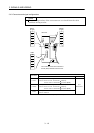
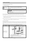
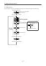
(a) Electromagnetic brake interlock (MBR)
This signal is output from the CN3 connector of the interface unit. This signal allows you to select
the axis number of the drive unit to be used with IFU parameter No. 10.
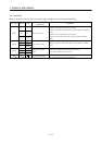
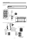
Axis 8
Electromagnetic brake interlock output axis number selection
Choose the axis number of the drive unit
that will use electromagnetic brake interlock output (MBR).
Setting
Selected Axis
All connected axes
Axis 1
Axis 2
Axis 3
Axis 4
Axis 5
Axis 6
Axis 7
8
0
1
2
3
4
5
6
7
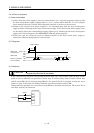
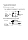
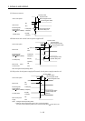
1) When selecting the corresponding axis number
The timing chart of the corresponding axis is the same as in (4) of this section.
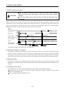
2) When using all axes
The timing chart in (4)(a) of this section changes as described below.
When the base circuits of all connected axes turn on, electromagnetic brake interlock (MBR)
turns on. If the servo on command timings differ between the axes, the axis whose servo on
occurred first will result in overload alarm. Hence, the servo on command should be given to all
axes at the same timing.
The others are as shown in (4) of this section.