


3 - 16
3. SIGNALS AND WIRING
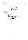
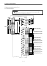
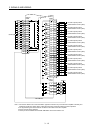
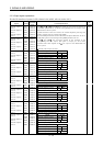
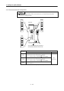
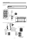
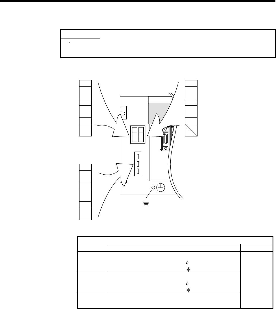
3.4.2 Connectors and signal configurations
POINT
The pin configurations of the connectors are as viewed from the cable
connector wiring section.
1
3
2
2
3
1
N
P
C
L
3
L
2
L1
1
2
3
L
11
L
21
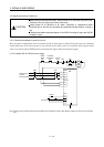
CNP1A
Base unit
(X type) (Y type)
The connector frames are connected to
the PE (earth) terminal of the base unit.
CNP1B
CNP3
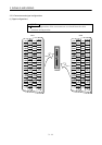
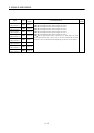
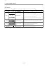
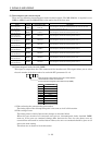
Cable side connector
Connector
Model Maker
CNP1A
Housing: 1-178128-3 (X type)
Contact: 917511-2 (max. sheath OD: 2.8[mm])
353717-2 (max. sheath OD:
3.4[mm]) (Note)
CNP1B
Housing: 2-178128-3 (Y type)
Contact: 917511-2 (max. sheath OD: 2.8[mm])
353717-2 (max. sheath OD:
3.4[mm]) (Note)
CNP3
Housing: 1-179958-3
Contact: 316041-2
Tyco
Electronics
Note. This contact is not included in the option (MR-J2MCNM).