


11 - 2
11. CHARACTERISTICS
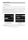
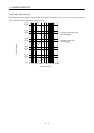
11.2 Power supply equipment capacity and generated loss
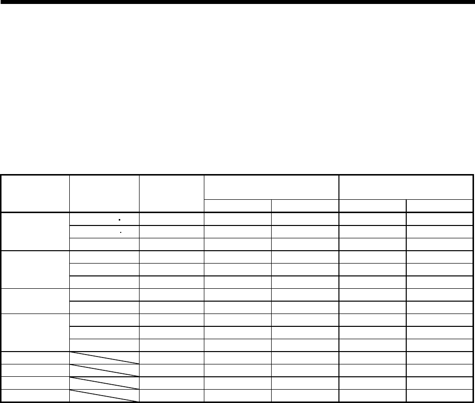
(1) Amount of heat generated by the drive unit
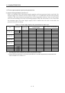
Table 11.1 indicates drive unit's power supply capacities and losses generated under rated load. For
thermal design of an enclosure, use the values in Table 11.1 in consideration for the worst operating
conditions. The actual amount of generated heat will be intermediate between values at rated torque
and servo off according to the duty used during operation. When the servo motor is run at less than
the maximum speed, the power supply capacity will be smaller than the value in the table, but
generated heat will not change.
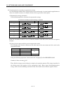
Table 11.1 Power supply capacity and generated heat at rated output
(Note 2)
Generated heat[W]
Area required for heat dissipation
Unit Servo motor
(Note 1)
Power supply
capacity[kVA]
At rated torque At servo off [m
2
] [ft
2
]
HC-KFS053 13 0.3 11 6 0.2 2.16
HC-MFS053 13 0.3 11 6 0.2 2.16
MR-J2M-10DU
HC-UFS13 0.3 11 6 0.2 2.16
HC-KFS23 0.5 14 6 0.3 3.24
HC-MFS23 0.5 14 6 0.3 3.24
MR-J2M-20DU
HC-UFS23 0.5 14 6 0.3 3.24
HC-KFS43 0.9 20 6 0.4 4.32
MR-J2M-40DU
HC-MFS43 0.9 20 6 0.4 4.32
HC-KFS73 1.3 40 6 0.7 7.54
HC-MFS73 1.3 40 6 0.7 7.54MR-J2M-70DU
HC-UFS73 1.3 40 6 0.7 7.54
MR-J2M-P8B 0.1 9 9 0.2 2.16
MR-J2M-BU4 0 4 4 0.1 1.08
MR-J2M-BU6 0 4 4 0.1 1.08
MR-J2M-BU8 0 4 4 0.1 1.08
Note 1. Note that the power supply capacity will vary according to the power supply impedance.
This value applies to the case where the power factor improving reactor is not used.
2. Heat generated during regeneration is not included in generated heat. To calculate heat generated by the regenerative brake
option, use Equation 12.1 in Section 12.1.1.