


5 - 20
5. PARAMETERS
Classifi-
cation
No. Symbol Name and Function
Initial
Value
Unit
Setting
Range
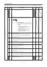
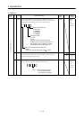
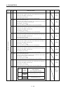
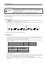
11 *SL1 Slot 1 axis number selection
Choose the axis number of the drive unit connected to the first slot
of the base unit. (Refer to Section 2.8)
Axis number
set value 1
In the initial setting, the first axis is set to the first slot.
0000 0000
to
0007h
12 *SL2 Slot 2 axis number selection
Choose the axis number of the drive unit connected to the second
slot of the base unit. (Refer to Section 2.8)
Axis number
set value 1
In the initial setting, the second axis is set to the second slot.
0001 0000
to
0007h
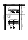
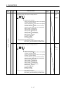
13 *SL3 Slot 3 axis number selection
Choose the axis number of the drive unit connected to the third slot
of the base unit. (Refer to Section 2.8)
Axis number
set value 1
In the initial setting, the third axis is set to the third slot.
0002 0000
to
0007h
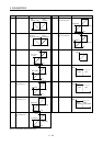
14 *SL4 Slot 4 axis number selection
Choose the axis number of the drive unit connected to the fourth slot
of the base unit. (Refer to Section 2.8)
Axis number
set value 1
In the initial setting, the fourth axis is set to the fourth slot.
0003 0000
to
0007h
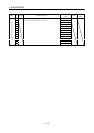
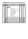
15 *SL5 Slot 5 axis number selection
Choose the axis number of the drive unit connected to the fifth slot
of the base unit. (Refer to Section 2.8)
Axis number
set value 1
In the initial setting, the fifth axis is set to the fifth slot.
0004 0000
to
0007h
16 *SL6 Slot 6 axis number selection
Choose the axis number of the drive unit connected to the sixth slot
of the base unit. (Refer to Section 2.8)
Axis number
set value 1
In the initial setting, the sixth axis is set to the sixth slot.
0005 0000
to
0007h
17 *SL7 Slot 7 axis number selection
Choose the axis number of the drive unit connected to the seventh
slot of the base unit. (Refer to Section 2.8)
Axis number
set value 1
In the initial setting, the seventh axis is set to the seventh slot.
0006 0000
to
0007h
18 *SL8 Slot 8 axis number selection
Choose the axis number of the drive unit connected to the eighth slot
of the base unit. (Refer to Section 2.8)
Axis number
set value 1
In the initial setting, the eighth axis is set to the eighth slot.
0007 0000
to
0007h
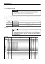
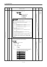
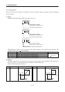
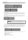
IFU parameter write inhibit
Setting
Setting
operation
Operation from unit operation section or
MR Configurator
(servo configuration software)
Reference0000
(initial
value)
Write
IFU parameter No. 1 to 19
Reference
000A
Write
IFU parameter No. 19
Basic IFU parameters
19 *BLK 0000 Refer to
name
and
function
column.