


1 - 2
1. FUNCTIONS AND CONFIGURATION
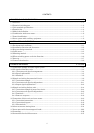
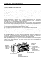
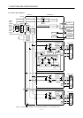
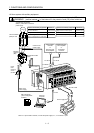
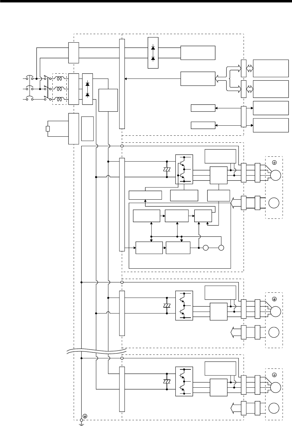
1.2 Function block diagram
W
RS-232C
D/A
NFB MC
U
V
W
M
L11
L
21
L1
L2
L
3
CNP3
P
N
C
CNP1A
U
V
M
CN1ACN1BCN3CNP2CN2CNP2CN2
W
U
V
M
CNP2CN2
CON3A-3H CON3A-3H CON3A-3H
FR-BAL
Power
supply
3-phase
200 to
230VAC
(Note)
1-phase
200 to
230VAC
Base unit Interface unit
I/F Control
I/F Control
Controller or
Servo amplifier
Servo amplifier
or termination
connector
Personal
computer
Analog monitor
(3 channels)
Regenerative brake option
Regener-
ative TR
Drive unit
Dynamic
brake
Servo motor
Inrush
current
suppression
circuit
Current
detector
Overcurrent
protection
Current
detection
Base amplifier
Actual position
control
Actual speed
control
Current
control
Model position
control
Model speed
control
Virtual
encoder
Virtual
servo
motor
Drive unit
Encoder
Drive unit
Dynamic
brake
Servo motor
Encoder
Current
detection
Dynamic
brake
Current
detection
Servo motor
Encoder
Position
command
input
Model
position
Model
speed
Model
torque
Position command
Note. For 1-phase 200 to 230VAC, connect the power supply to L
1
, L
2
and leave L
3
open.
CNP1B
(Earth)
(Earth)
(Earth)