


3 - 40
3. SIGNALS AND WIRING
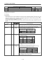
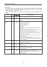
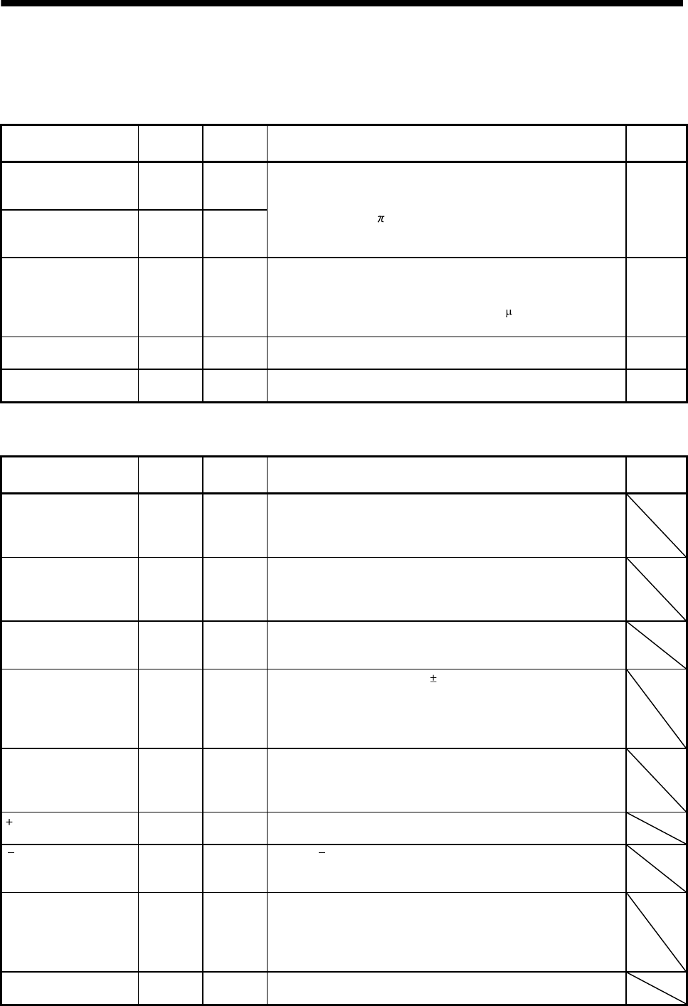
3.5.3 Output signals
Refer to section 3.8.2 for the output interfaces (symbols in the I/O Division field in the table) of the
corresponding connector pins.
Signal Symbol
Connector
pin No.
Functions/Applications I/O division
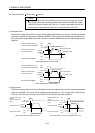
Encoder A-phase pulse
(differential line driver)
LA
LAR
CN6-11
CN6-24
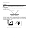
Outputs pulses per servo motor revolution set in parameter No. PA15
in the differential line driver system. In CCW rotation of the servo
motor, the encoder B-phase pulse lags the encoder A-phase pulse
by a phase angle of
/2. The relationships between rotation direction
and phase difference of the A- and B-phase pulses can be changed
using parameter No. PC19.
DO-2
Encoder B-phase pulse
(differential line driver)
LB
LBR
CN6-12
CN6-25
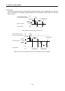
Encoder Z-phase pulse
(differential line driver)
LZ
LZR
CN6-13
CN6-26
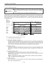
Outputs the zero-point signal of the encoder in the differential line
driver system. One pulse is output per servo motor revolution. This
signal turns on when the zero-point position is reached. (Negative
logic)The minimum pulse width is about 400
s. For home position
return using this pulse, set the creep speed to 100r/min. or less.
DO-2
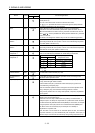
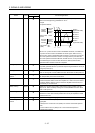
Analog monitor 1
MO1 CN20-4
Used to output the data set in parameter No. Po13 to across MO1-
LG in terms of voltage. Resolution 12 bits
Analog
output
Analog monitor 2
MO2 CN20-14
Used to output the data set in parameter No. Po14 to across MO2-
LG in terms of voltage. Resolution 12 bits
Analog
output
3.5.4 Power supply
Signal Symbol
Connector
pin No.
Functions/Applications I/O division
Servo amplifier digital I/F
power supply input
DICOM CN6-5
Used to input 24VDC (24VDC 10% 150mA) for I/O interface of the
servo amplifier. The power supply capacity changes depending on
the number of I/O interface points to be used. Connect the positive
terminal of the 24VDC external power supply for the sink interface.
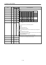
Servo amplifier digital I/F
common
DOCOM CN6-17
Common terminal for input signals such as DOG and EMG of the
servo amplifier. Pins are connected internally. Separated from LG.
Connect the positive terminal of the 24VDC external power supply for
the source interface.
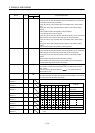
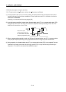
MR-HDP01 open
collector power input OPC CN6-18
When using the MR-HDP01 manual pulse generator, connect OPC
and DICOMD, and supply OPC with the positive (+) voltage of
24VDC.
MR-HDP01 digital I/F
power supply input
DICOMD
CN10-13
CN10-14
Used to input 24VDC (24VDC
10% 800mA) for I/O interface of the
MR-J3-D01. The power supply capacity changes depending on the
number of I/O interface points to be used. Connect the positive
terminal of the 24VDC external power supply for the sink interface.
Pins are connected internally.
MR-HDP01 digital I/F
common
DOCOMD CN10-37
Common terminal for input signals such as SON and RES of the MR-
J3-D01. Pins are connected internally. Separated from LG. Connect
the positive terminal of the 24VDC external power supply for the
source interface.
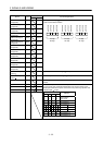
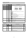
15VDC power supply
P15R CN20-13
Outputs +15VDC to across P15R-LG. Available as power for TLA,
VC. Permissible current: 30mA
12VDC power supply
N12R CN20-15
Outputs 12VDC to across N12R-LG. Available as power for VC.
However, there is an individual difference of about -12 to -15V in the
voltage. Permissible current: 30mA
Control common
LG
CN6-23
CN20-1
CN20-9
CN20-11
CN30-1
Common terminal for TLA, VC, VLA, OP, MO1, MO2 and P15R. Pins
are connected internally.
Shield
SD
CN10-50
Plate
Connect the external conductor of the shield cable.