


6
13.14 Surge absorbers (recommended) ..................................................................................................... 13-73
13.15 Noise reduction techniques ............................................................................................................... 13-74
13.16 Leakage current breaker.................................................................................................................... 13-81
13.17 EMC filter (recommended) ................................................................................................................ 13-83
13.18 MR-HDP01 manual pulse generator ................................................................................................. 13-88
13.19 MR-DS60 6-digit digital switch........................................................................................................... 13-90
13.20 External digital display (MR-DP60) ................................................................................................... 13-93
13.21 Junction terminal block PS7DW-20V14B-F (recommended) ........................................................... 13-95
13.22 Junction terminal block MR-TB50 ..................................................................................................... 13-97
14. COMMUNICATION FUNCTION 14- 1 to 14-50
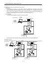
14.1 Configuration ......................................................................................................................................... 14- 1
14.2 Communication specifications .............................................................................................................. 14- 3
14.2.1 Communication overview ............................................................................................................... 14- 3
14.2.2 Parameter setting ........................................................................................................................... 14- 4
14.3 Protocol ................................................................................................................................................. 14- 5
14.3.1 Transmission data configuration .................................................................................................... 14- 5
14.3.2 Character codes ............................................................................................................................. 14- 6
14.3.3 Error codes ..................................................................................................................................... 14- 7
14.3.4 Checksum ....................................................................................................................................... 14- 7
14.3.5 Time-out operation ......................................................................................................................... 14- 8
14.3.6 Retry operation ............................................................................................................................... 14- 8
14.3.7 Initialization ..................................................................................................................................... 14- 9
14.3.8 Communication procedure example.............................................................................................. 14- 9
14.4 Command and data No. list ................................................................................................................. 14-10
14.4.1 Read commands ........................................................................................................................... 14-10
14.4.2 Write commands ........................................................................................................................... 14-15
14.5 Detailed explanations of commands ................................................................................................... 14-18
14.5.1 Data processing ............................................................................................................................ 14-18
14.5.2 Status display ................................................................................................................................ 14-20
14.5.3 Parameters .................................................................................................................................... 14-21
14.5.4 External I/O signal statuses (DIO diagnosis) ............................................................................... 14-24
14.5.5 Device ON/OFF ............................................................................................................................. 14-29
14.5.6 Disable/enable of I/O devices (DIO) ............................................................................................. 14-30
14.5.7 Input devices ON/OFF (test operation) ........................................................................................ 14-31
14.5.8 Test operation mode ..................................................................................................................... 14-32
14.5.9 Alarm history .................................................................................................................................. 14-39
14.5.10 Current alarm .............................................................................................................................. 14-40
14.5.11 Point table .................................................................................................................................... 14-41
14.5.12 Servo amplifier group designation .....................................................................................
......... 14-48
14.5.13 Other commands ......................................................................................................................... 14-49
APPENDIX App.- 1 to App.- 5
App. 1 Parameter list ..................................................................................................................................App.- 1
App. 2 Signal layout recording paper ........................................................................................................App.- 4
App. 3 Change of connector sets to the RoHS compatible products .......................................................App.- 5
App. 4 MR-J3-200T-RT servo amplifier.....................................................................................................App.- 6
App. 5 Selection example of servo motor power cable .......................................................................... App.-10