


3 - 29
3. SIGNALS AND WIRING
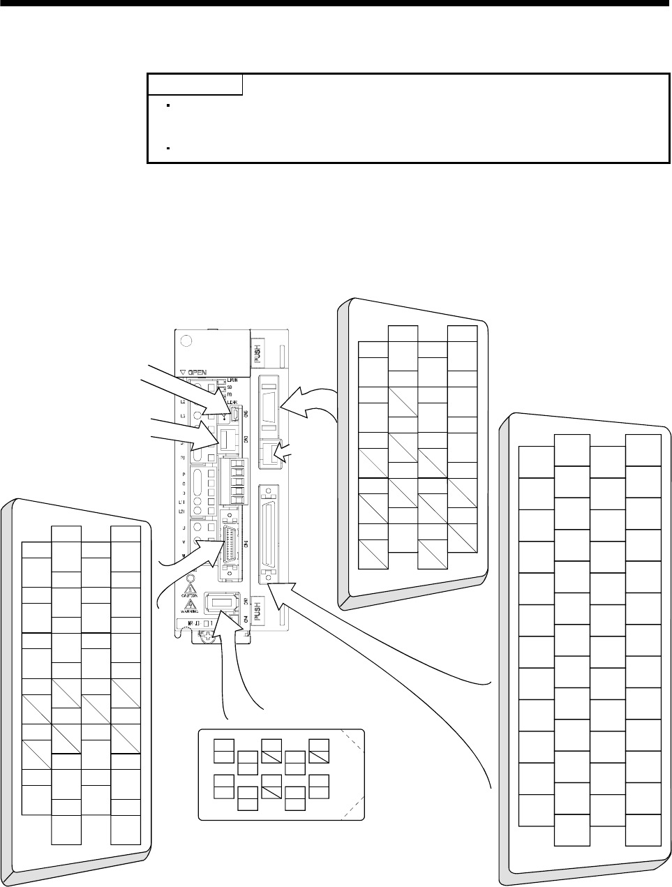
3.4 Connectors and signal arrangements
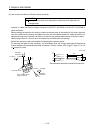
POINT
The pin configurations of the connectors are as viewed from the cable
connector wiring section.
Refer to (3) in this section for CN10 signal assignment.
Refer to section 3.5 for details of each signal (device).
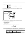
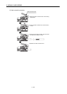
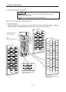
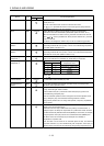
(1) Signal arrangement
The servo amplifier front view shown is that of the MR-J3-10T and the MR-J3-D01. Refer to chapter 11
Outline Drawings for the appearances and connector layouts of the other servo amplifiers.
2
4
6
8
10
12
14
16
18
20
22
24
1
3
5
7
9
11
13
15
17
19
21
23
27
29
31
33
35
37
39
41
43
45
47
49
26
28
30
32
34
36
38
40
42
44
46
48
25 50
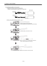
CN10
CN6
114
215
RD
DICOM
DOG
ALM
316
LSP
LSN
ZP
DOCOM
417
5
6
8
10
12
7
9
11
13
19
21
23
25
18
20
22
24
26
LB
LA
LZ
LG
LBR
LAR
LZR
EMG
PP NP
OPC
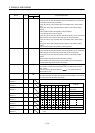
CN20
111
212
LG
VC
313
414
5
6
8
10
7
9
16
18
20
15
17
19
TLA
LG
P15R
N12R
MO1 MO2
LG
CN30
external
digital
display
CN3
MR-PRU03 parameter unit
For the signal arrangements, refer
to this section (3).
CN5 (USB connector)
Personal computer
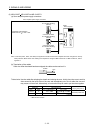
The 3M make connector is shown.
When using any other connector,
refer to section 13.1.2.
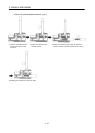
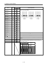
4
MRR
2
LG 8
6
1
P5
5
10
3
MR
7
9
BAT
CN2
MDR
MD