


3 - 30
3. SIGNALS AND WIRING
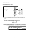
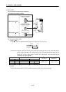
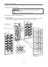
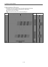
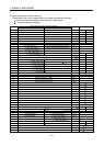
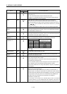
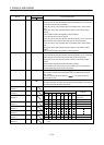
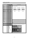
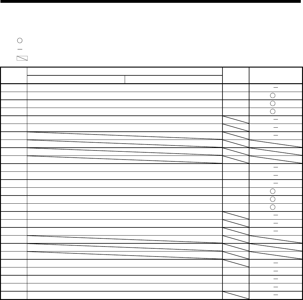
(2) Signal arrangement of CN6 connector
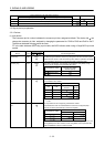
The symbols in the Device change column in the table represent the followings.
: The device can be changed by the parameters in parentheses.
: The device cannot be changed.
: For manufacturer setting. Do not connect anything to it.
Pin No.
Device assigned in the initial status (Symbol)
I/O division Device change
When using the point table When using the BCD input
1 Forced stop (EMG) DI-1
2 Proximity dog (DOG) DI-1 (PD06)
3 Forward rotation stroke end (LSP) DI-1 (PD07)
4 Reverse rotation stroke end (LSN) DI-1 (PD08)
5 Digital I/F power supply input (DICOM)
6 Manual pulse generator (PP)
7
8
9
10
11 Encoder A-phase pulse (LA) DO-2
12 Encoder B-phase pulse (LB) DO-2
13 Encoder Z-phase pulse (LZ) DO-2
14 Ready (RD) DO-1 (PD09)
15 Trouble (ALM) DO-1 (PD10)
16 Home position return completion (ZP) DO-1 (PD11)
17 Digital I/F common (DOCOM)
18 Manual pulse generator open collector power input (OPC)
19 Manual pulse generator input (NP)
20
21
22
23 Control common (LG)
24 Encoder A-phase pulse (LAR) DO-2
25 Encoder B-phase pulse (LBR) DO-2
26 Encoder Z-phase pulse (LZR) DO-2
Plate Shield (SD)