


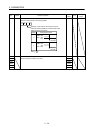
5 - 44
5. PARAMETERS
5.5.3 Analog monitor
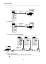
The servo status can be output to two channels in terms of voltage. The servo status can be monitored using
un ammeter.
(1) Setting
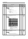
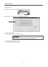
Change the following digits of parameter No. Po13, Po14.
Analog monitor (MO1) output selection
(Signal output to across MO1-LG)
Analog monitor (MO2) output selection
(Signal output to across MO2-LG)
Parameter No. Po13
000
000
Parameter No. Po14
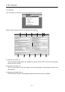
Parameters No. Po15 and Po16 can be used to set the offset voltages to the analog output voltages. The
setting range is between
9999 and 9999mV.
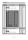
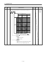
Parameter No. Description Setting range [mV]
Po15 Used to set the offset voltage for the analog monitor 1 (MO1).
9999 to 9999
Po16 Used to set the offset voltage for the analog monitor 2 (MO2).
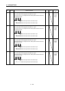
(2) Set content
The servo amplifier is factory-set to output the servo motor speed to analog monitor 1 (MO1) and the torque
to analog monitor (MO2). The setting can be changed as listed below by changing the parameter No. Po13
and Po14 value.
Refer to (3) for the measurement point.
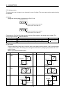
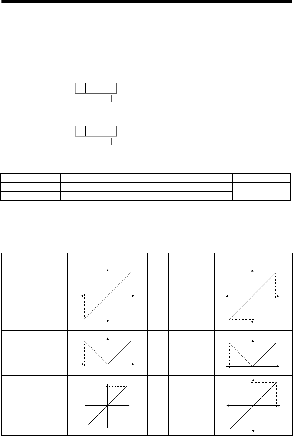
Setting Output item Description Setting Output item Description
0 Servo motor
speed
Max. speed
CW direction
CCW direction
Max. speed
0
8[V]
-8[V]
1 Torque (Note 2)
Max. torque
Driving in CW
direction
Driving in CCW
direction
Max. torque
0
8[V]
-8[V]
2 Servo motor
speed
CCW direction
Max. speed Max. speed0
8[V]
CW direction
3 Torque (Note 2)
Driving in CCW
direction
Max. torque
Max. torque0
8[V]
Driving in CW
direction
4 Current command
Max. current command
(Max. torque command)
C
W
d
ir
ec
ti
o
n
CCW direction
Max. current command
(Max. torque command)
0
8[V]
-8[V]
5 Speed command
CW direction
CCW direction
0
10[V]
-10[V]
Max. speed
Max. speed