


1
CONTENTS
1. FUNCTIONS AND CONFIGURATION 1 - 1 to 1 -38
1.1 Introduction ............................................................................................................................................... 1 - 1
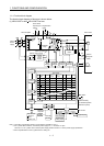
1.1.1 Function block diagram ..................................................................................................................... 1 - 2
1.1.2 System configuration ......................................................................................................................... 1 - 5
1.2 Servo amplifier standard specifica tions ................................................................................................... 1 - 7
1.3 Function list ............................................................................................................................................. 1 -11
1.4 Model code definition .............................................................................................................................. 1 -13
1.4.1 Servo amplifier ................................................................................................................................. 1 -13
1.4.2 MR-J3-D01 extension I/O unit ......................................................................................................... 1 -14
1.5 Combination with servo motor ................................................................................................................ 1 -15
1.6 Structure .................................................................................................................................................. 1 -16
1.6.1 Parts identification ............................................................................................................................ 1 -16
1.6.2 Removal and reinstallation of the front cover .................................................................................. 1 -22
1.6.3 Installation and removal of MR-J3-D01 ........................................................................................... 1 -25
1.7 Configuration including auxiliary equipment .......................................................................................... 1 -30
2. INSTALLATION 2 - 1 to 2 - 4
2.1 Installation direction and clearances ....................................................................................................... 2 - 1
2.2 Keep out foreign materials ....................................................................................................................... 2 - 3
2.3 Cable stress ............................................................................................................................................. 2 - 3
2.4 Inspection items ....................................................................................................................................... 2 - 4
2.5 Parts having service lives ........................................................................................................................ 2 - 4
3. SIGNALS AND WIRING 3 - 1 to 3 -68
3.1 Input power supply circuit ........................................................................................................................ 3 - 2
3.2 I/O signal connection diagram ................................................................................................................ 3 -10
3.2.1 Positioning operation using the point table...................................................................................... 3 -10
3.2.2 BCD input positioning operation with the digital switch .................................................................. 3 -12
3.2.3 BCD input positioning operation with the programmable controller ............................................... 3 -15
3.3 Explanation of power supply system ...................................................................................................... 3 -18
3.3.1 Signal explanations .......................................................................................................................... 3 -18
3.3.2 Power-on sequence ......................................................................................................................... 3 -19
3.3.3 CNP1, CNP2, CNP3 wiring method ................................................................................................ 3 -21
3.4 Connectors and signal arrangements .................................................................................................... 3 -29
3.5 Signal (device) explanation ..................................................................................................................... 3 -32
3.5.1 Devices ............................................................................................................................................. 3 -32
3.5.2 Input signals ..................................................................................................................................... 3 -39
3.5.3 Output signals................................................................................................................................... 3 -40
3.5.4 Power supply .................................................................................................................................... 3 -40
3.6 Detailed description of signals (devices) ................................................................................................ 3 -41
3.6.1 Forward rotation start
reverse rotation start temporary stop/restart ........................................... 3 -41
3.6.2 Movement finish
rough match in position .................................................................................... 3 -42
3.6.3 Torque limit ....................................................................................................................................... 3 -44
3.7 Alarm occurrence timing chart ................................................................................................................ 3 -46