3 - 31
3. SIGNALS AND WIRING
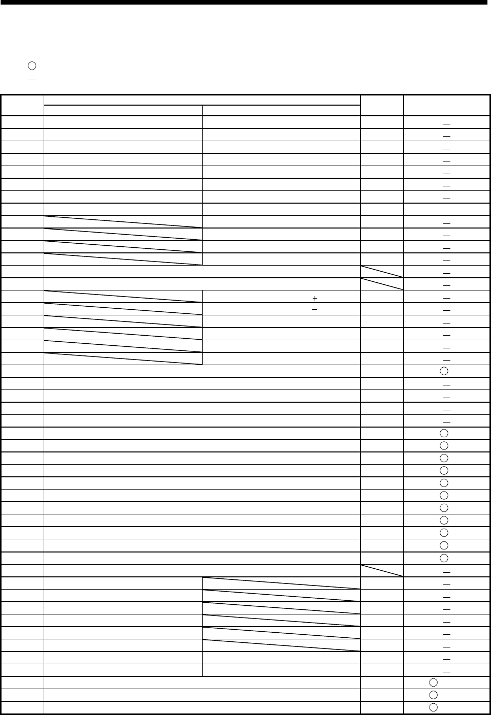
(3) Signal arrangement of CN10 connector
The symbols in the Device change column in the table represent the followings.
: The device can be changed by the parameters in parentheses.
: The device cannot be changed.
Pin No.
Device assigned in the initial status (Symbol)
I/O division Device change
When using the point table When using the BCD input
1 Point table No.1 (DI0) Position data input 1 (POS00) (Note 3) DI-1
2 Point table No.2 (DI1) Position data input 2 (POS01) (Note 3) DI-1
3 Point table No.3 (DI2) Position data input 3 (POS02) (Note 3) DI-1
4 Point table No.4 (DI3) Position data input 4 (POS03) (Note 3) DI-1
5 Point table No.5 (DI4) Position data input 5 (POS10) (Note 3) DI-1
6 Point table No.6 (DI5) Position data input 6 (POS11) (Note 3) DI-1
7 Point table No.7 (DI6) Position data input 7 (POS12) (Note 3) DI-1
8 Point table No.8 (DI7) Position data input 8 (POS13) (Note 3) DI-1
9 Position data input 9 (POS20) (Note 3) DI-1
10 Position data input 10 (POS21) (Note 3) DI-1
11 Position data input 11 (POS22) (Note 3) DI-1
12 Position data input 12 (POS23) (Note 3) DI-1
13 Digital I/F power supply input (DICOMD)
14 Digital I/F power supply input (DICOMD)
15 Position data input symbol (POSP) DI-1
16 Position data input symbol (POSN) DI-1
17 Strobe (STRB) DI-1
18 Speed selection 1 (SP0) (Note 3) DI-1
19 Speed selection 2 (SP1) (Note 3) DI-1
20 Speed selection 3 (SP2) (Note 3) DI-1
21 Servo-on (SON) DI-1 (Po02)
22 Alarm code output 1 (ACD0) DO-1
23 Alarm code output 2 (ACD1) DO-1
24 Alarm code output 3 (ACD2) DO-1
25 Alarm code output 4 (ACD3) DO-1
26 Reset (RES) DI-1 (Po02)
27 External torque limit selection (TL) DI-1 (Po03)
28 Internal torque limit selection (TL1) DI-1 (Po03)
29 Manual pulse generator multiplication 1 (TP0) DI-1 (Po04)
30 Manual pulse generator multiplication 2 (TP1) DI-1 (Po04)
31 Override selection (OVR) DI-1 (Po05)
32 Automatic/manual selection (MD0) DI-1 (Po05)
33 Temporary stop/Restart (TSTP) DI-1 (Po06)
34 Proportion control (PC) DI-1 (Po06)
35
Forward rotation start (ST1)
DI-1 (Po07)
36 Reverse rotation start (ST2) DI-1 (Po07)
37 Digital I/F common (DOCOMD)
38 M code 1 (MCD00) DO-1
39 M code 2 (MCD01) DO-1
40 M code 3 (MCD02) DO-1
41 M code 4 (MCD03) DO-1
42 M code 5 (MCD10) DO-1
43 M code 6 (MCD11) DO-1
44 M code 7 (MCD12) Position data request 1 (PRQ1) DO-1
45 M code 8 (MCD13) Position data request 2 (PRQ2) DO-1
46 Temporary stop (PUS) DO-1 (Po08)
47 Movement finish (MEND) DO-1 (Po08)
48 Rough match (CPO) DO-1 (Po09)


