


1 - 2
1. FUNCTIONS AND CONFIGURATION
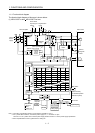
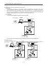
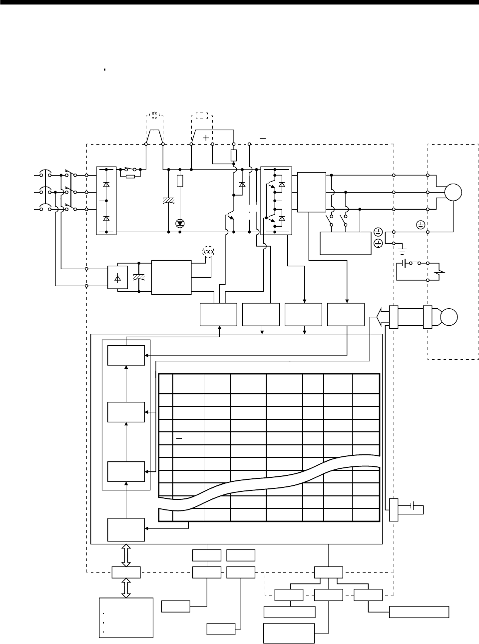
1.1.1 Function block diagram
The function block diagram of this servo is shown below.
(1) MR-J3-350T or less
MR-J3-200T4 or less
(Note 3) Cooling fan
W
NFB MC
L
1
L2
L3
L
11
L21
B2
CN2
U
V
W
U
V
M
B1
CN4
MR-J3BAT
P
1
P
2
1
No.
1000
1000
80
80 0 0
2
2000
2000
100
100 0 0
3
4000
2000
70
60 500 1
4
2000
60
70 1000 1
5
1000
2000
80
80 0 0
6
2000
1000
80 80 0 0
7
1000
1000
80
80 0 0
8
1000 1000
100
100 0 0
1000
1000
100
100 0 0
255 2000
2000
80
80 0 0
USB
CN3CN5
CN6
MR-J3-D01
RS-422
USB
RS-422
0
1
99
5
7
2
20
27
99
CN10 CN20 CN30
Analog input
Analog output
Digital display
Servo motor
Power factor
improving DC
reactor
Electro-
magnetic
brake
Encoder
500
Current
detection
Overcurrent
protection
Voltage
detection
Base
amplifier
Current
control
Speed
control
Position
control
Position
command
creation
Personal
computer
Controller
Dynamic
brake
Servo amplifier
Optional battery
(for absolute position
detection system)
Point table
M code
Dwell
Position
data
Speed
Acceleration
time
constant
Deceleration
time
constant
CHARGE
lamp
Control
circuit
power
supply
D
C
(Note1)
Current
detector
Regene-
rative
TR
Auxiliary
Model adaptive control
DI/O Control
DI/O Control
Servo on
Start
Failure, etc
(Note 2)
Power
supply
Diode
stack
Relay
P( )
Regenerative
option
N( )
(MR-J3-70T or more)
Note 1. The built-in regenerative resistor is not provided for the MR-J3-10T (1).
2. For 1-phase 200 to 230VAC, connect the power supply to L
1, L2 and leave L3 open.
There is no L
3 for 1-phase 100 to 120VAC power supply. Refer to section 1.2 for the power supply specification.
3. Servo amplifiers MR-J3-70T or greater have a cooling fan.