


1 - 19
1. FUNCTIONS AND CONFIGURATION
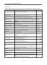
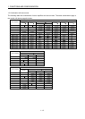
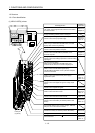
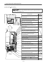
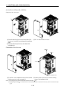
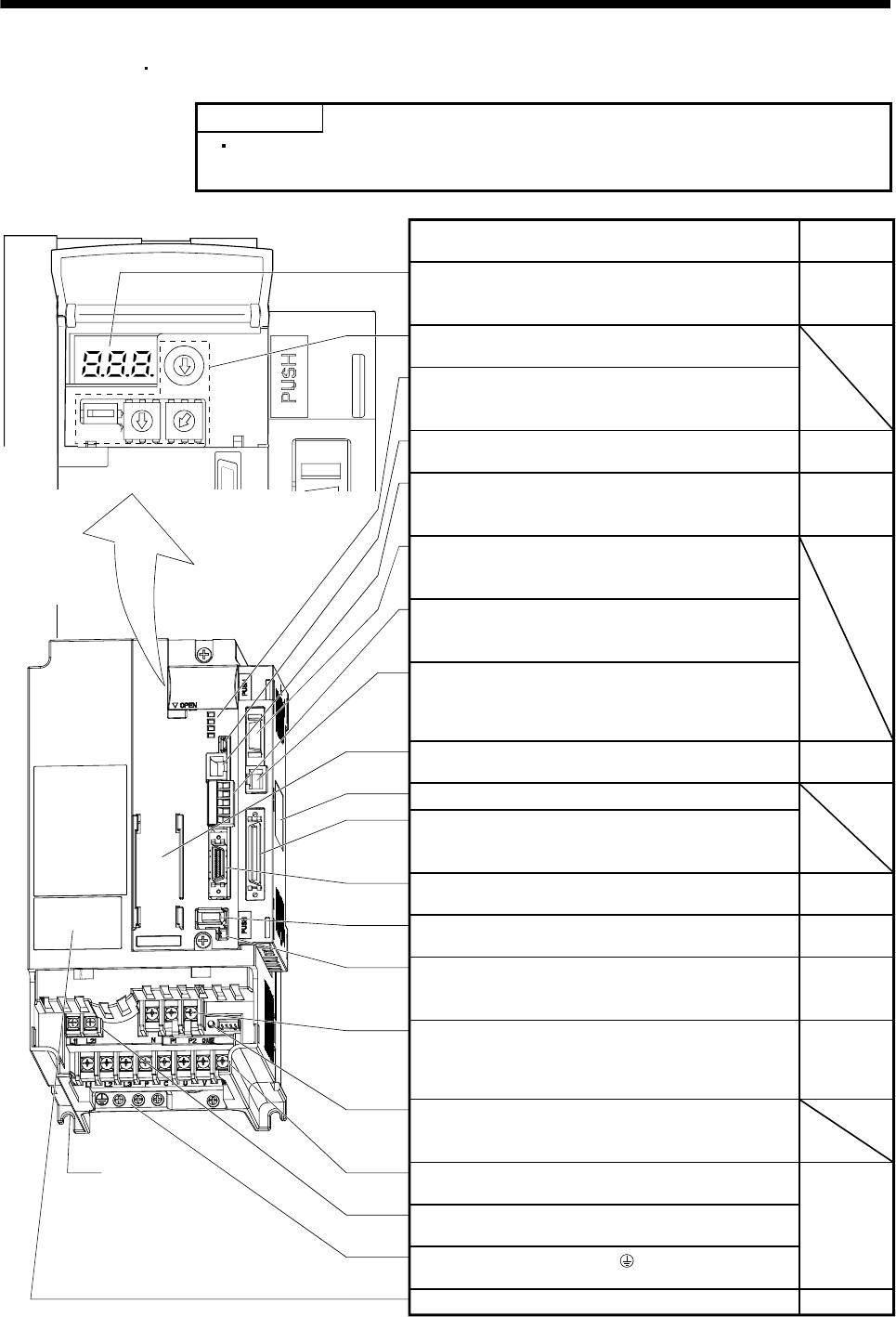
(4) MR-J3-350T4
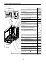
MR-J3-500T(4)
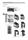
POINT
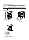
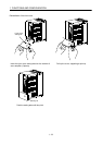
The servo amplifier is shown without the front cover. For removal of the front
cover, refer to section 1.6.2.
5
4
3
2
1
0
9
8
7
6
5
4
3
2
1
0
9
8
7
6
5
4
3
2
1
0
9
8
7
6
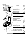
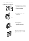
Cooling fan
Fixed part
(4 places)
Section 4.9
Battery holder
Contains the battery for absolute position data backup.
Name/Application
Detailed
Explanation
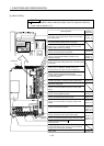
Section 4.3
Chapter 10
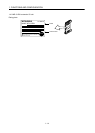
When using in combination with MR-J3-D01, do not
change the setting (default) shown in the figure.
Communication alarm display section
When using in combination with MR-J3-D01, the LED
display does not have any meaning.
Chapter 6
Chapter 6
Chapter 7
Chapter 14
Analog input connector (CN20)
Used to connect the analog torque limit or override analog
input signal.
RS-422 communication connector (CN3)
Used to connect the MR-PRU03 parameter unit or
personal computer.
USB communication connector (CN5)
Used to connect the personal computer.
Display
The 3-digit, seven-segment LED shows the servo status
and alarm number.
Digital display connector (CN30)
Used to connect the MR-DP60 digital display.
The MR-PRU03 parameter unit or a personal computer
cannot be connected.
CC-Link connector (CN1)
When using in combination with MR-J3-D01, this
connector is not used. Do not connect anything to it.
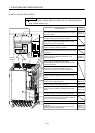
MR-J3-D01 rating plate
Section 3.2
Section 3.4
Section 3.10
Section 13.1
Section 4.9
Section 13.7
Battery connector (CN4)
Used to connect the battery for absolute position data
backup.
Encoder connector (CN2)
Used to connect the servo motor encoder.
I/O signal connector (CN6)
Used to connect digital I/O signals.
I/O signal connector (CN10)
Used to connect the digital I/O signal or analog output
signal.
DC reactor terminal block(TE3)
Used to connect the DC reactor.
Charge lamp
Lit to indicate that the main circuit is charged. While this
lamp is lit, do not reconnect the cables.
Section 1.4
Protective earth (PE) terminal ( )
Ground terminal.
Rating plate
Main circuit terminal block (TE1)
Used to connect the input power supply and servo motor.
Control circuit terminal block (TE2)
Used to connect the control circuit power supply.
Section 3.1
Section 3.3
Section 11.1
Section 3.1
Section 3.3
Section 11.1
Section 13.11