


3 - 19
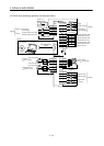
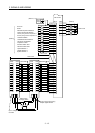
3. SIGNALS AND WIRING
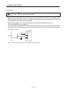
3.3.2 Power-on sequence
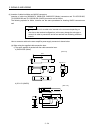
(1) Power-on procedure
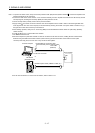
1) Always wire the power supply as shown in above section 3.1 using the magnetic contactor with the
main circuit power supply (three-phase: L
1
, L
2
, L
3
, single-phase: L
1
, L
2
). Configure up an external
sequence to switch off the magnetic contactor as soon as an alarm occurs.
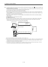
2) Switch on the control circuit power supply L
11, L21 simultaneously with the main circuit power supply
or before switching on the main circuit power supply. If the main circuit power supply is not on, the
display shows the corresponding warning. However, by switching on the main circuit power supply,
the warning disappears and the servo amplifier will operate properly.
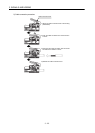
3) The servo amplifier can accept the servo-on (SON) about 1 to 2s after the main circuit power supply
is switched on. Therefore, when servo-on (SON) is switched on simultaneously with the main circuit
power supply, the base circuit will switch on in about 1 to 2s, and the ready (RD) will switch on in
further about 5ms, making the servo amplifier ready to operate. (Refer to paragraph (2) in this
section.)
4) When the reset (RES) is switched on, the base circuit is shut off and the servo motor shaft coasts.
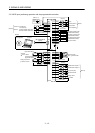
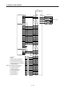
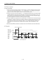
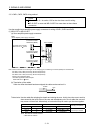
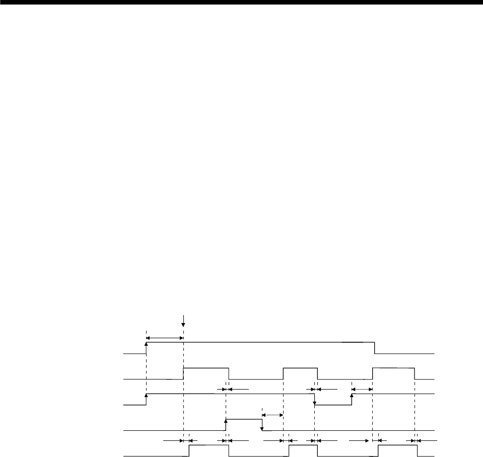
(2) Timing chart
95ms
95ms
OFF
ON
OFF
ON
ON
OFF
OFF
ON
OFF
ON
10ms5ms
10ms
10ms5ms
10ms
5ms 10ms
(2 to 2.5s)
Servo-on (SON) accepted
Main circuit
Control circuit
Power supply
Base circuit
Servo-on
(SON)
Reset
(RES)
Ready
(RD)
Power-on timing chart