


10 - 7
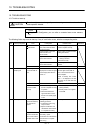
10. TROUBLESHOOTING
Display Name Definition Cause Action
A33 Overvoltage The following shows
the input value of
converter bus
voltage.
MR-J3-
T(1):
400VDC or more
MR-J3-
T4:
800VDC or more
1. Regenerative option is not used. Use the regenerative option.
2. Though the regenerative option is
used, the parameter No.PA02
setting is "
00 (not used)".
Set correctly.
3. Lead of built-in regenerative resistor
or regenerative option is open or
disconnected.
1. Change the lead.
2. Connect correctly.
4. Regenerative transistor faulty. Change the servo amplifier
5. Wire breakage of built-in
regenerative resistor or regenerative
option
1. For wire breakage of built-in regenerative
resistor, change the servo amplifier.
2. For wire breakage of regenerative option,
change the regenerative option.
6. Capacity of built-in regenerative
resistor or regenerative option is
insufficient.
Add regenerative option or increase
capacity.
7. Power supply voltage high. Check the power supply.
8. Ground fault occurred in servo
motor power (U, V, W).
Correct the wiring.
9. The jumper across BUE-SD of the
FR-BU2 brake unit is removed.
Fit the jumper across BUE-SD.
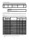
A35 Command pulse
frequency error
Input pulse
frequency of the
command pulse is
too high.
1. Pulse frequency of the manual
pulse generator is too high.
Change the pulse frequency to a proper
value.
2. Noise entered the pulses of the
manual pulse generator.
Take action against noise.
3. Manual pulse generator failure Change the manual pulse generator.
A37 Parameter error Parameter setting is
wrong.
1. Servo amplifier fault caused the
parameter setting to be rewritten.
Change the servo amplifier.
2. Regenerative option not used with
servo amplifier was selected in
parameter No.PA02.
Set parameter No.PA02 correctly.
3. Value outside setting range has
been set in electronic gear.
Set parameters No. PA06, PA07 correctly.
4. Opposite sign has been set in
software limit increasing side
(parameters No. PC31, PC32).
Similarly, opposite sign has been set
in software limit decreasing side
(parameters No. PC33, PC34).
Set parameters No. PC31 to PC34 correctly.
5. Opposite sign has been set in
position range output address
increasing side (parameters No.
PC37, PC38). Similarly, opposite
sign has been set in position range
output address decreasing side
(parameters No. PC39, PC40).
Set parameters No. PC37 to PC40 correctly.
6. The number of write times to EEP-
ROM exceeded 100,000 due to
parameter write, etc.
Change the servo amplifier.
7. The torque limit switching dog
system or torque limit switching data
set system is selected for home
position return in the point table
positioning operation. (Parameter
No. PC02)
These home position return types cannot be
used. Set the parameter No.PC02 correctly.
Point table setting is
wrong.
8. Setting value is out of the setting
range.
Set it correctly.