


4 - 28
4. OPERATION
4.5.4 Automatic operation by BCD (3 digits
2) input with the programmable controller
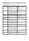
The positioning is executed the positioning based on the positioning data set with the programmable controller
and the selected speed command. For the connection example of the programmable controller to the servo
amplifier, refer to section 3.2.3.
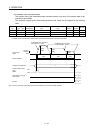
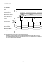
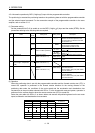
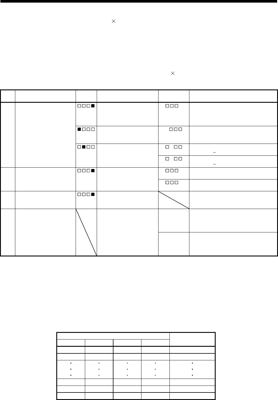
(1) Parameter setting
Set the parameter No.Po10 to enable to use the BCD (3 digits
2) input and the strobe (STRB). Set the
parameters referring to the following table as required.
No. Name
Digit to
be set
Setting item Setting value Description
Po10 Function selection O-1 Operation system 2 Make sure to set the operation system.
Make the I/O devices required for the
BCD input valid. For devices to be valid,
refer to section 3.4.
Strobe signal 0
Make sure to set the strobe (STRB).
A strobe signal is required if the
programmable controller is used.
Symbol of the positioning
data in the BCD positioning
0 Uses the 6-digit positioning data without
symbol (+/
).
1
(initial value)
Uses the 6-digit positioning data with
symbol (+/
).
PA01 Control mode Command system
(Refer to section 5.1.3.)
0
(initial value)
Selects the absolute value command
system.
1 Selects the incremental value command
system.
PA05 Feeding function selection
(Feed length multiplication
STM)
Feed length multiplication
(Refer to section 5.1.7.)
Refer to section 5.1.7.
PA14 Rotation direction selection Servo motor rotation
direction
(Refer to section 5.1.12.)
0
(initial value)
Forward rotation start (ST1) ON: rotates
in the CCW direction.
Reverse rotation start (ST2) ON: rotates
in the CW direction.
1 Forward rotation start (ST1) ON: rotates
in the CW direction.
Reverse rotation start (ST2) ON: rotates
in the CCW direction
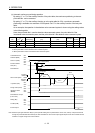
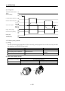
(2) Operation
When the positioning data is set with the programmable controller and the forward rotation start (ST1) is
turned ON, operation is performed in the forward rotation direction for the moving distance of the
positioning data under the conditions of the motor speed and the acceleration and deceleration time
constants set to the point tables selected with SP0 to 3. In the incremental command system, operation is
performed in the reverse direction when the reverse rotation start (ST2) is turned ON.
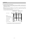
Select the point table with SP0 to 3 as shown below and execute the positioning based on the set motor
speed, acceleration and deceleration time constants.
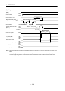
(Note) Device Point table No. to
be selected
SP3 SP2 SP1 SP0
0 0 0 1 1
0 0 1 0 2
1 1 0 1 13
1 1 1 0 14
1 1 1 1 15
Note. 0: OFF
1: ON