5 - 41
5. PARAMETERS
No. Symbol Name and function
Initial
value
Unit
Setting
range
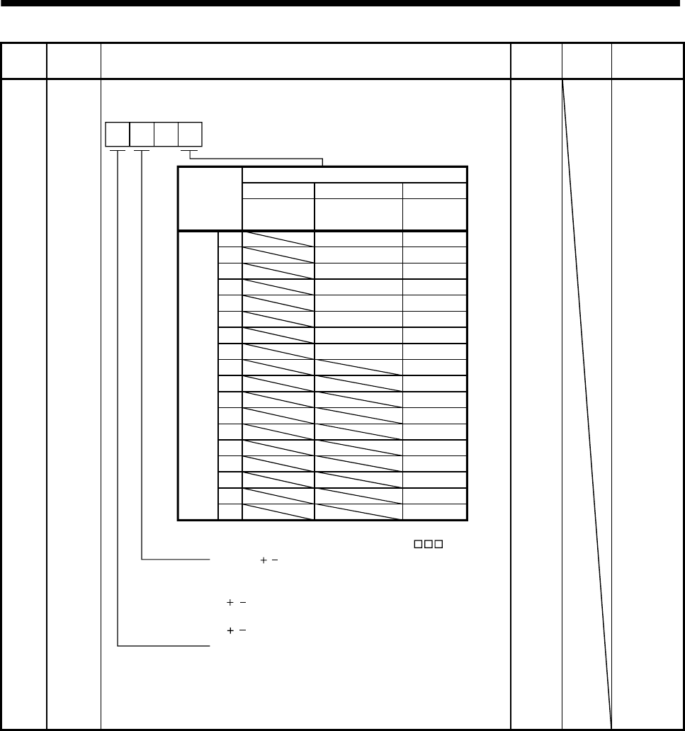
Po10 *OOP1 Function selection O-1
Select the positioning operation by point table selection and BCD input.
0
CN10
Pin No.
Setting value
BCD input
used
1
2
3
4
5
6
7
8
9
10
11
12
15
16
0
DI0
17
18
19
20
Point table used
12
DI1
DI2
DI3
DI4
DI5
DI6
DI7
POS00
POS01
POS02
POS03
POS10
POS11
POS12
POS13
POS20
POS21
POS22
POS23
POSP
POSN
STRB(Note)
SP0
SP1
SP2
Devices not
assigned
Strobe signal
0: Invalid
For the BCD input by the programmable controller
1: Valid
For the point table or MR-DS60 digital switch
Symbol ( / ) of the positioning data in the BCD
positioning
0: Invalid
/ symbol is not used.
1: Valid
/ symbol is used.
Note. When using the strobe input (STRB),
set the fourth digit of this parameter in "0 ".
2101h Refer to
name and
function
column.


