


3 - 47
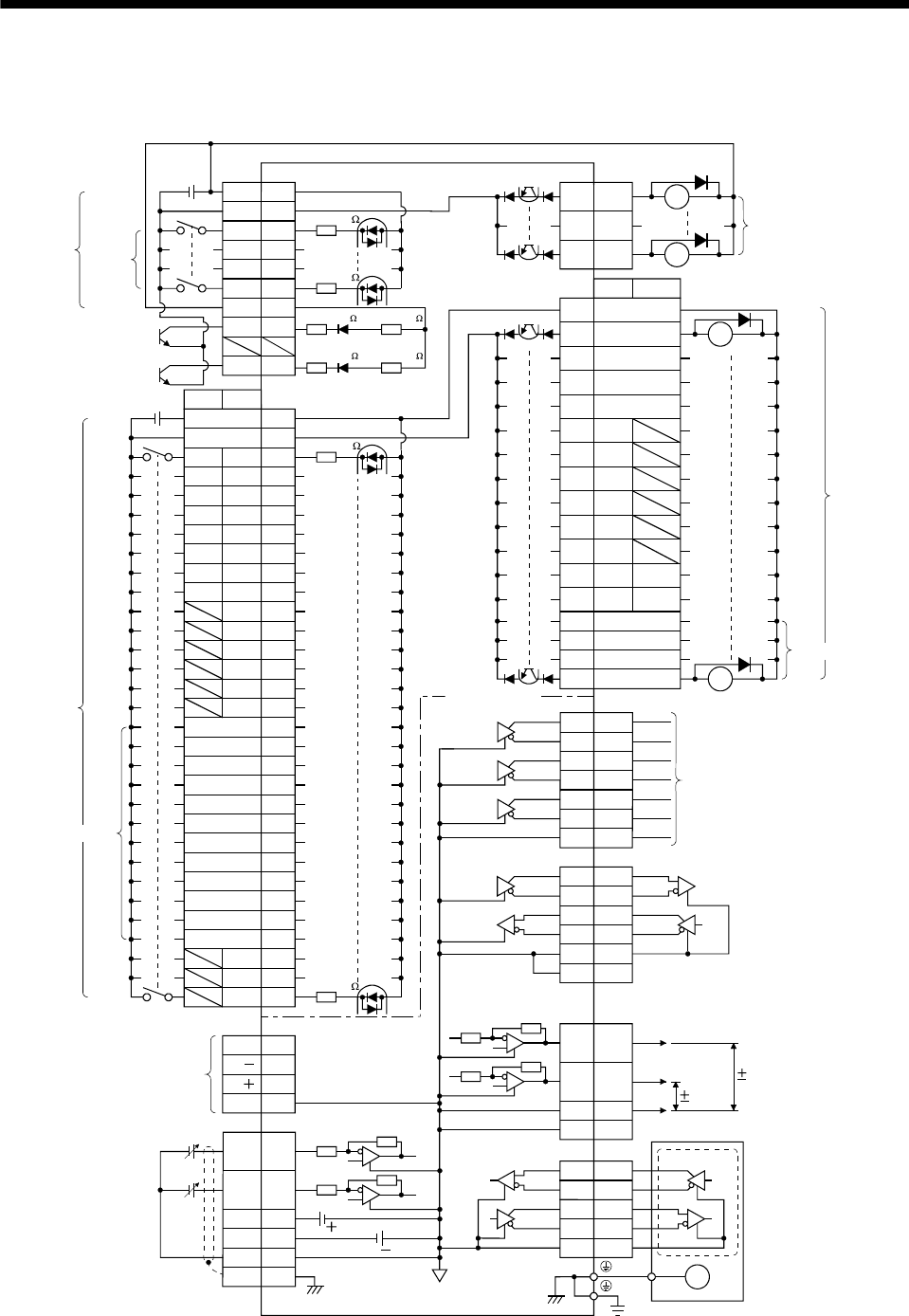
3. SIGNALS AND WIRING
3.8 Interface
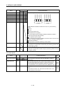
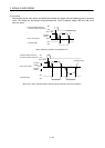
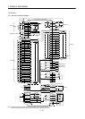
3.8.1 Internal connection diagram
CN6
14
15
16
RD
ALM
ZP
RA
RA
<Isolated>
11
24
12
25
13
26
LA
LAR
LB
LBR
LZ
LZR
23 LG
CN6
Differential line
driver output
(35mA or less)
12VDC
CN20
2VC
12TLA
13
P15R
9LG
Plate
SD
15
N12R
15VDC
5
4
3
6
1
7
CN3
SDP
SDN
RDP
RDN
LG
LG
RS-422
3
CN2
2
4
7
8
MR
MRR
MD
MDR
LG
E
M
Servo motor
Encoder
USB
D
GND
VBUS
D
1
2
3
5
CN5
CN20
MO1
MO2
LG
4
14
11
Analog monitor
10VDC
10VDC
LG1
EMG
CN6
1
DOG 2
LSP 3
LSN 4
Approx.5.6k
5
17
DICOM
DOCOM
24VDC
Approx.5.6k
CN10
14
22
23
49
DICOMD
ACD0
ACD1
INP
RA
RA
6
19
OPC
18
PP
NP
Approx.100k
Approx.100k
Approx.1.2k
Approx.1.2k
Dedicated to MR-HP01
POS00
CN10
1
2
3
4
Approx.5.6k
13
37
DICOMD
24VDC
5
6
7
8
9
10
11
12
15
POSP
16
POSN
21
RES 26
TL 27
TL1 28
TP0 29
TP1 30
OVR 31
MD0 32
TSTP 33
PC 34
ST1 35
ST2 36
SP0 18
SP1 19
SP2 20
Approx.5.6k
DI4
DI5
DI6
DI7
DI1
DI2
DI3
DOCOMD
POS01
POS02
POS03
POS10
POS11
POS12
POS13
POS20
POS21
POS22
POS23
SON
DI0
24 ACD2
25 ACD3
38
39
40
41
42
43
44
45
46 PUS
47 MEND
48 CPO
MCD12
MCD11
MCD10
MCD03
MCD02
MCD01
MCD00
PT BCD
PT BCD
(Note 1)
(Note 2)
MCD13
PRO0
PRO1
Servo amplifier + MR-J3-D01
(Note 2)
(Note 1, 2)
(Note 2)
(Note 1)
(Note 1)
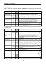
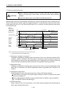
Note 1. Devices assigned to these pins can be changed in the parameter settings.
2. For this sink I/O interface. For the source I/O interface, refer to section 3.8.3.