


1 - 5
1. FUNCTIONS AND CONFIGURATION
1.1.2 System configuration
This section provides operations using this servo.
The configuration can be freely arranged as any system from a single axis system to an up to 32-axis system.
In addition, the optimum device to each system can be assigned to the connector pin of the I/F part. (Refer to
section 3.4.) To change or assign devices, it is necessary to set parameter No. PD06 to 11 and Po02 to 09. Set
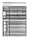
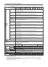
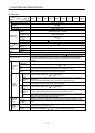
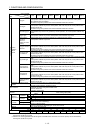
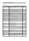
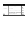
the following values to the point table.
Name Setting range Unit
Position data 999999 to 999999
0.001[mm]
0.01[mm]
0.1[mm]
1[mm]
Servo motor speed 0 to max. speed [r/min]
Acceleration time constant 0 to 20000 [ms]
Deceleration time constant 0 to 20000 [ms]
Dwell 0 to 20000 [ms]
Auxiliary function 0 to 3
There are 31 points of point tables to be used when 1 station is occupied and 255 points when 2 stations are
occupied.
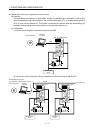
(1) Operation by external input signals
(a) Definition
The following shows a configuration example when all devices are controlled by external input signals.
The signals consist of the I/O signals in the factory setting.
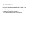
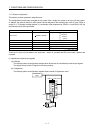
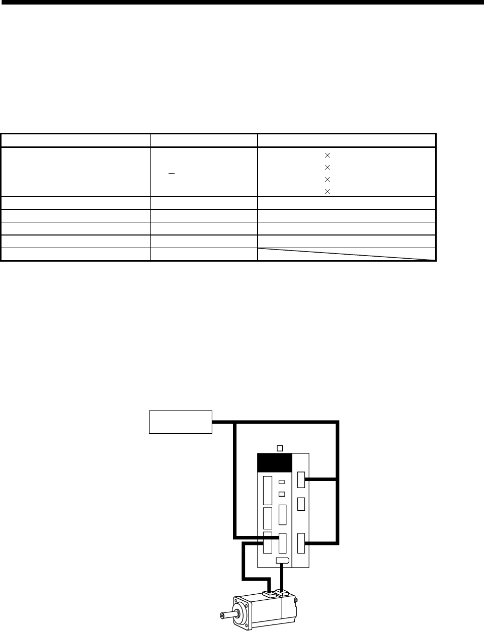
(b) Configuration
The following shows a configuration diagram when external I/O signals are used.
MR-J3- T MR-J3-D01
CNP3
External I/O
signal
CN2
CN6
CN1
CN3
CN5
CN10
CN20
CN30