


3 - 50
3. SIGNALS AND WIRING
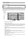
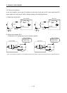
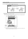
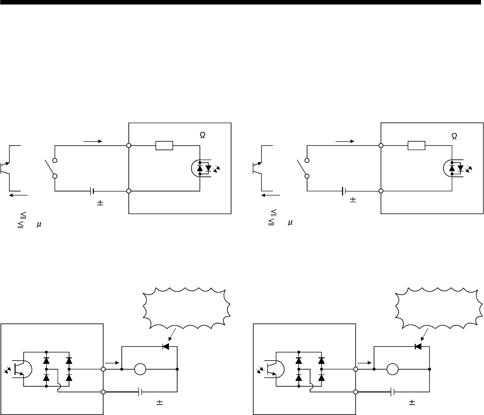
3.8.3 Source I/O interfaces
In this servo amplifier, source type I/O interfaces can be used. In this case, all DI-1 input signals and DO-1
output signals are of source type. Perform wiring according to the following interfaces.
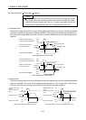
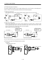
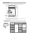
(1) Digital input interface DI-1
EMG,
etc.
Servo amplifier
Switch
Approx. 5mA
DICOM
V
CES 1.0V
I
CEO
100
A
24VDC 10%
150mA
Approx. 5.6k
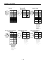
MR-J3-D01
DICOMD
SON,
etc.
Switch
Approx. 5mA
V
CES 1.0V
I
CEO
100
A
24VDC 10%
800mA
Approx. 5.6k
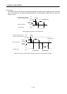
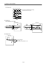
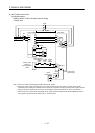
(2) Digital output interface DO-1
A maximum of 2.6V voltage drop occurs in the servo amplifier.
(Note) 24VDC 10%
150mA
If polarity of diode is
reversed, servo
amplifier will fail.
Servo amplifier
ALM,
etc.
Load
DOCOM
(Note) 24VDC 10%
800mA
If polarity of diode is
reversed, servo
amplifier will fail.
MR-J3-D01
INP,
etc.
Load
DOCOM
Note. If the voltage drop (maximum of 2.6V) interferes with the relay operation, apply high voltage (up to 26.4V) from external source.